3. Architecture
3.1. Overview
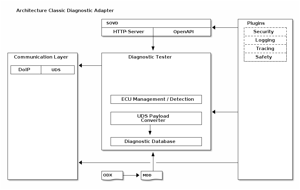
3.1.1. SOVD
The SOVD block manages incoming SOVD requests and translates them into calls to the Diagnostic Tester API. It includes an HTTP server to receive SOVD requests and an OpenAPI generator to create documentation for API endpoints.
Additionally, the OpenAPI generator can be used as a standalone component to generate comprehensive documentation for ECU variants.
The functionality is divided into three distinct modules:
HTTP Server
Translation between SOVD and Diagnostic Tester API
OpenAPI Generation
3.1.2. Diagnostic Tester
The Diagnostic Tester component provides an API for plugins and the SOVD layer. This API handles UDS payload conversion, manages ECU variant detection, and maintains the diagnostic runtime database.
It encapsulates functionality similar to a traditional offboard tester, optimized for the SOVD use case, and supports only the UDS protocol.
3.1.2.1. Diagnostic runtime database
The diagnostic runtime database is consulted to translate named parameters and services into UDS. It contains all diagnostic descriptions (.mdd) of the ECUs provided at startup and allows for runtime switches and additions/removal of underlying diagnostic descriptions, while no active diagnostic communication is in progress.
In terms of requirements, the database needs to minimize memory consumption while delivering maximum performance for the most common calls.
3.1.2.2. API
In the diagnostic tester, an API needs to be provided to utilize its functionality. The API itself needs to be close to the MCD-3 D specification, to enable future use-cases of the diagnostic tester core.
3.1.2.3. UDS payload conversion
As an internal module, the UDS payload conversion is mainly responsible to convert a set of named input parameters (Diagnostic Service, request parameters) into a UDS payload, and also back from UDS payload into named parameters.
3.1.3. Plugins
Plugins are responsible for significant portions of the CDAs functionality which are often vendor specific. As an example, security through jwt tokens is solved differently by different vendors, so the mechanism for their verification and interpretation into access rights needs to be customizable.
The same is true for logging, tracing and safety. Lastly, vendors might want to add custom endpoints with custom functionality, which would also be done through plugins.
3.1.4. Communication Layer
In the communication layer everything related to the communication with ECUs is handled. This includes periodically sent tester presents, timing and connection parameters. It provides an API to logically communicate with ECUs using their addresses (functional/physical) and handles the execution order, parallelization and link state.
3.1.4.1. UDS
Implementation of UDS communication, with handling of NRCs, tester presents (either physical or functional, flag for every connection per address), timeouts, retries and actual data.
3.1.4.2. DoIP
Implementation of DoIP communication with handling of timeouts.
3.2. General
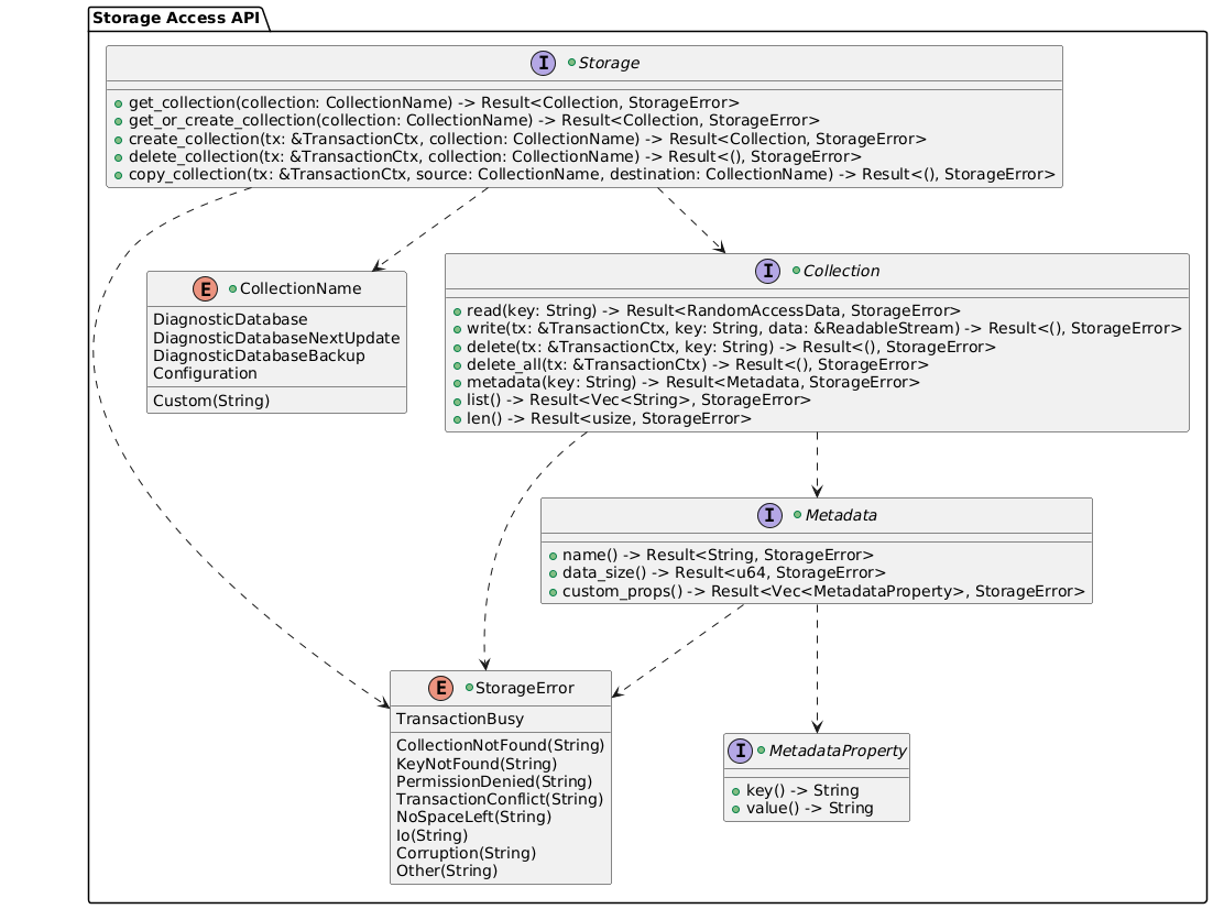
3.2.1. Storage Access
The Storage Access API provides an abstraction layer for storage access, allowing the CDA to interact with different types of storage systems (e.g., local file system, databases) without being tightly coupled to a specific implementation. To achieve atomicity and consistent behavior across different storage implementations, the API defines the following semantics:
A transaction context shall be created through a If all operations succeed, the transaction will be committed, and the result will be a success. Should an unexpected interruption event (power-off, reset) occur during a transaction, the transaction must be rolled back on the next startup, to ensure consistency of the storage state. For reading data, random access to the data must be supported, to allow for efficient reading of arbitrary chunks without needing to load it entirely into memory. This might be required for memory efficient handling of the diagnostic database. The |
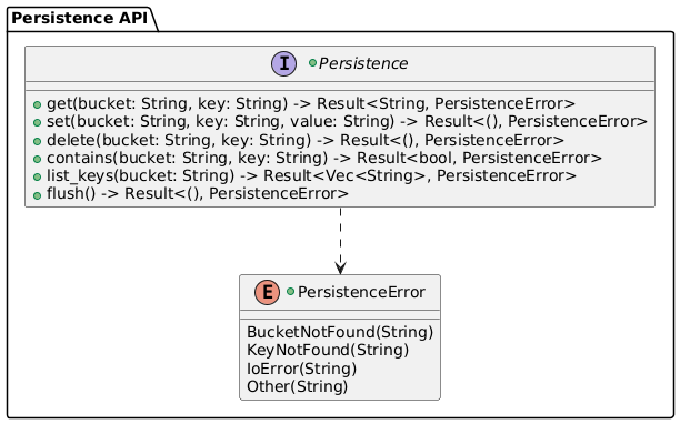
3.2.2. Persistence
The Persistence API provides a durable key-value storage abstraction. Data is organized into Buckets, each representing a named, logically separated set of key-value pairs. The API is accessed through an exchangeable provider, enabling different storage backends without affecting consuming code.
The The Providers are exchangeable at compile time, allowing the use of alternative backends (e.g., an in-memory provider for testing purposes) without modifying consuming code. |
Software Architecture: Default redb Persistence Provider arch~system-default-redb-persistence-provider
|
The default persistence provider uses redb as its storage backend. It implements the
|
3.2.3. Systemd Watchdog Integration
The systemd watchdog integration is implemented as an optional background task that bridges the CDA health system with the systemd service manager notification protocol. Startup Detection At initialization, the component checks whether the process was launched by systemd and whether the watchdog is enabled. If either condition is not met, no task is spawned and the CDA operates without watchdog integration. Notification Interval The notification interval is derived from the systemd-configured watchdog timeout, reduced by a safety margin to ensure notifications arrive before systemd considers the service unresponsive. Health Aggregation On each tick, the task queries all registered health providers and folds their individual statuses into a single aggregated status. The folding semantics are:
State Machine The notification sent to systemd is determined by the transition between the previous and current aggregated status:
Shutdown The task terminates gracefully when the application shutdown signal is received. |
![@startuml
[*] --> Starting
Starting --> Up : all providers healthy\n(notify: Ready)
Up --> Up : still healthy\n(notify: Watchdog)
Up --> Failed : provider degraded\n(notify: WatchdogTrigger)
@enduml](../_images/plantuml-7f2b8dd9c867ab148d17f0fe505fdbd26f94ca76.png)
3.3. SOVD-API
3.3.1. Introduction
Eclipse OpenSOVD Classic Diagnostic Adapter aims to be compatible with the ISO/DIS 17978-3:2025 SOVD standard.
This chapter specifies the specific implementation of that standard, as well as extensions to it, which are required for some use-cases.
3.3.2. HTTP
The SOVD-API is based on HTTP/1.1 as transport protocol, and available through an configurable TCP port. |
3.3.3. SOVD-API
3.3.3.1. Data Types
Data types must be mapped as follows:
Primitive JSON types All primitive JSON types (string, array, number, integer, boolean, and object) can be used. For strings, the following format identifiers can be used:
Note TODO More string formats required? Mapping of complex data types Note TODO Mapping of complex data types |
3.3.3.2. Bulk Data
Bulk-data endpoints allow the management of bulk data, like files that are to be used for flashing. Paths are required to be in the following structure:
Note IMPORTANT: All calls to the aforementioned endpoints can fail with reasonable HTTP status codes (e.g. 401, 403, 409, 501), depending on the context and state.
|
![' SPDX-FileCopyrightText: 2026 Copyright (c) Contributors to the Eclipse Foundation
'
' See the NOTICE file(s) distributed with this work for additional
' information regarding copyright ownership.
'
' This program and the accompanying materials are made available under the
' terms of the Apache License Version 2.0 which is available at
' https://www.apache.org/licenses/LICENSE-2.0
'
' SPDX-License-Identifier: Apache-2.0
@startuml
title Bulk-Data Endpoints
participant Client
participant "HTTP Server\n(Axum)" as HTTP
participant "Security\nMiddleware" as SEC
participant "Bulk-Data\nHandler" as HANDLER
participant "File System /\nStorage" as FS
== List entries ==
Client -> HTTP : GET /bulk-data/{category}
activate HTTP
HTTP -> SEC : authenticate & authorize
activate SEC
SEC -> HTTP : OK
deactivate SEC
HTTP -> HANDLER : route to bulk-data handler
activate HANDLER
HANDLER -> FS : list entries in category
activate FS
FS -> HANDLER : entries with IDs and metadata
deactivate FS
HANDLER -> HTTP : JSON body
deactivate HANDLER
HTTP -> Client : HTTP 200 OK\n{ "items": [ { "id": "...", ... }, ... ] }
deactivate HTTP
== Download entry ==
Client -> HTTP : GET /bulk-data/{category}/{entry-id}
activate HTTP
HTTP -> SEC : authenticate & authorize
activate SEC
SEC -> HTTP : OK
deactivate SEC
HTTP -> HANDLER : route to bulk-data handler
activate HANDLER
HANDLER -> FS : read entry data
activate FS
FS -> HANDLER : binary data
deactivate FS
HANDLER -> HTTP : binary response\n(MIME type determined by content)
deactivate HANDLER
HTTP -> Client : HTTP 200 OK\nContent-Type: <mime-type>\n<binary data>
deactivate HTTP
== Upload entry ==
Client -> HTTP : POST /bulk-data/{category}\nContent-Disposition: form-data\n<binary data>
activate HTTP
HTTP -> SEC : authenticate & authorize
activate SEC
SEC -> HTTP : OK
deactivate SEC
HTTP -> HANDLER : route to bulk-data handler
activate HANDLER
HANDLER -> FS : store data with metadata
activate FS
FS -> HANDLER : stored (entry-id)
deactivate FS
HANDLER -> HTTP : JSON body
deactivate HANDLER
HTTP -> Client : HTTP 201 Created\n{ "id": "<entry-id>" }
deactivate HTTP
== Delete entry ==
Client -> HTTP : DELETE /bulk-data/{category}/{entry-id}
activate HTTP
HTTP -> SEC : authenticate & authorize
activate SEC
SEC -> HTTP : OK
deactivate SEC
HTTP -> HANDLER : route to bulk-data handler
activate HANDLER
HANDLER -> FS : delete entry
activate FS
FS -> HANDLER : deleted
deactivate FS
HANDLER -> HTTP : success
deactivate HANDLER
HTTP -> Client : HTTP 204 No Content
deactivate HTTP
@enduml](../_images/plantuml-2f5a5ec5ff5b44e8ad403b02dedfb1ae35c273d8.png)
3.3.3.3. Entities
The GET /components Returns a list of all ECU entities that have been loaded from diagnostic descriptions (MDD files). Each item in the list contains the ECU name, a lowercase identifier, and a URI reference to the individual component resource. The response may include additional fields beyond the standard GET /components/{ecu-name} Returns detailed information about a specific ECU entity, including:
The connectivity state of an ECU reflects its current diagnostic reachability and variant detection status:
Optionally, diagnostic description metadata (SDGs) for the ECU can be included in the response through a query parameter. |
Software Architecture: Standardized Resource Collection Mapping arch~sovd-api-standardized-resource-collection-mapping
|
Every ECU with a This doesn’t include the |
3.3.3.4. ECU resource collection
Each ECU entity must provide a standardized resource collection as defined in ISO 17978-3, chapter 5.4.2. The resource collection for ECUs is defined in an OpenAPI Specification: |
3.3.3.5. SDG/SD Metadata
Special Data Groups (SDGs) and Special Data (SDs) from the diagnostic description can be retrieved through an
opt-in query parameter ECU-level SDGs On the Service-level SDGs On the Operation-level SDGs On the For asynchronous operations (which consist of multiple subfunctions such as Start, Stop, RequestResults),
each subfunction’s SDGs are returned as separate entries in the Data format The SDG/SD structure is recursive. Each entry in the list is one of two types:
SD and SDG entries are distinguished by their structure – an entry with a |
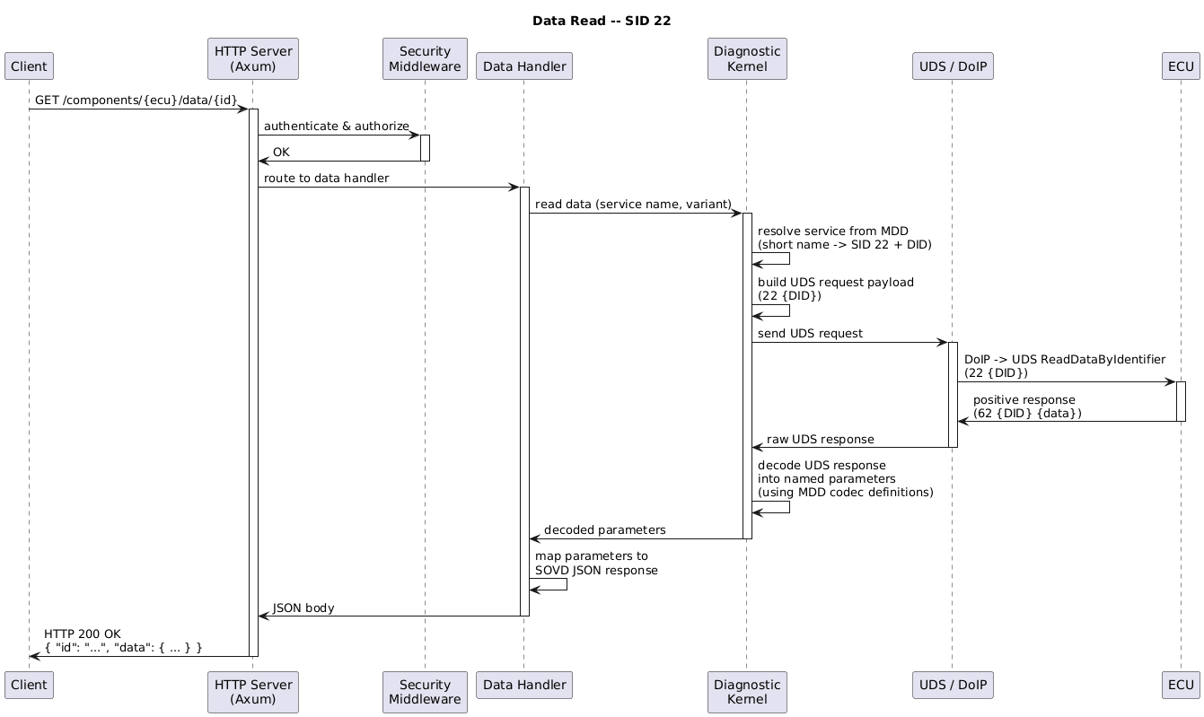
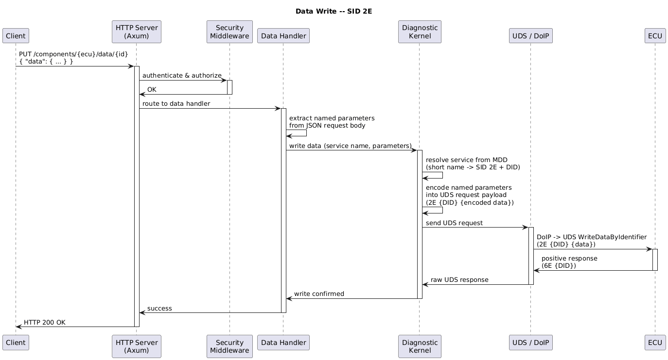
3.3.3.6. Data Resources – SID 2216 & 2E16
Data resources for ECUs are available in the standardized resource collection within the path The data main path returns a list of the data identifiers available as A data identifier in the list is described with the following attributes (all strings):
Naming Names for data resources are determined by taking all diag-services defined for 2216 and 2E16 – their short name is taken as a base and processed by removing configurable prefixes/suffixes, to determine the data identifier within the The following diagrams illustrate the message flow for reading and writing data resources:
|
3.3.3.7. Categories
The category of a data identifier must be mappable with configuration, in which the functional class name is mapped to a category name. The following standard categories are defined by the standard:
Additional custom categories must be prefixed with Services without a mapping should be ignored to allow a separation between configuration and data services. |
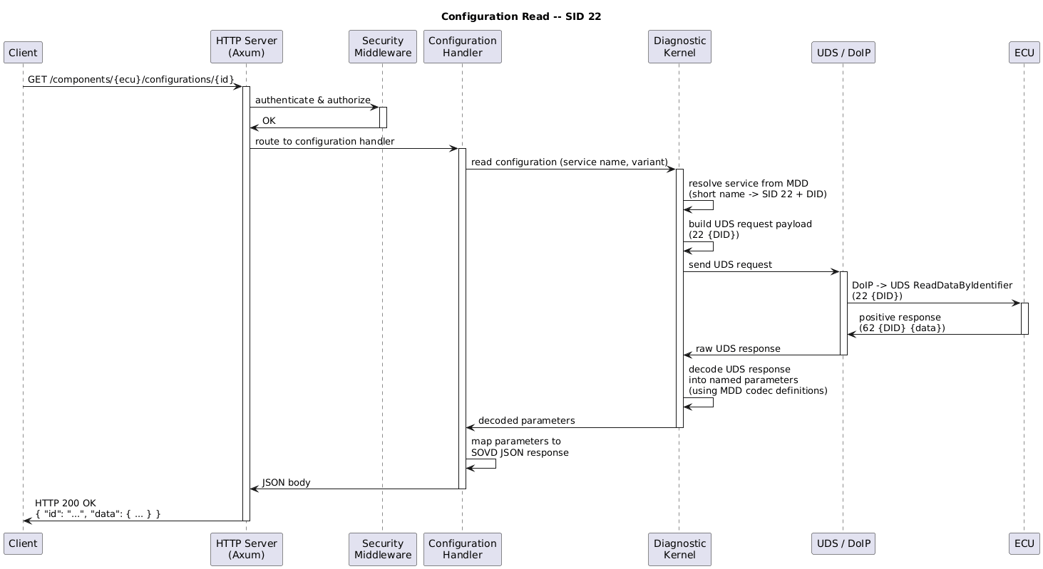
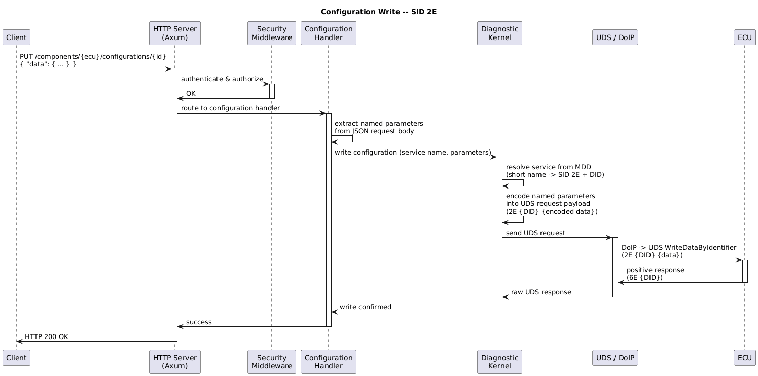
3.3.3.8. Configurations – SID 2216 & 2E16
Names for data resources are determined by taking all diag-services defined for 2216 and 2E16, and filtering
them for a configurable functional class name. Their short name is taken as a base and processed by removing
configurable prefixes/suffixes, to determine the data identifier within the The returned item properties for the
The following diagrams illustrate the message flow for reading and writing configuration resources:
Note
Rationale for serviceAbstract Coding data files might not include the matching name for a service, or detailed JSON parameters that would
be required to code an ECU. Therefore, a “reverse lookup” to the name can be required, so a client without
access to the diagnostic description is able to code an ECU just with the |
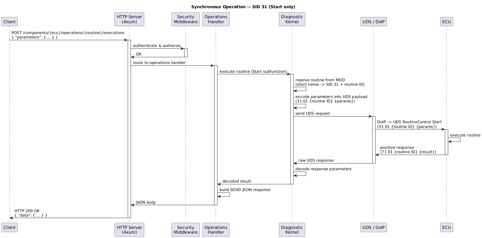
3.3.4. Operations
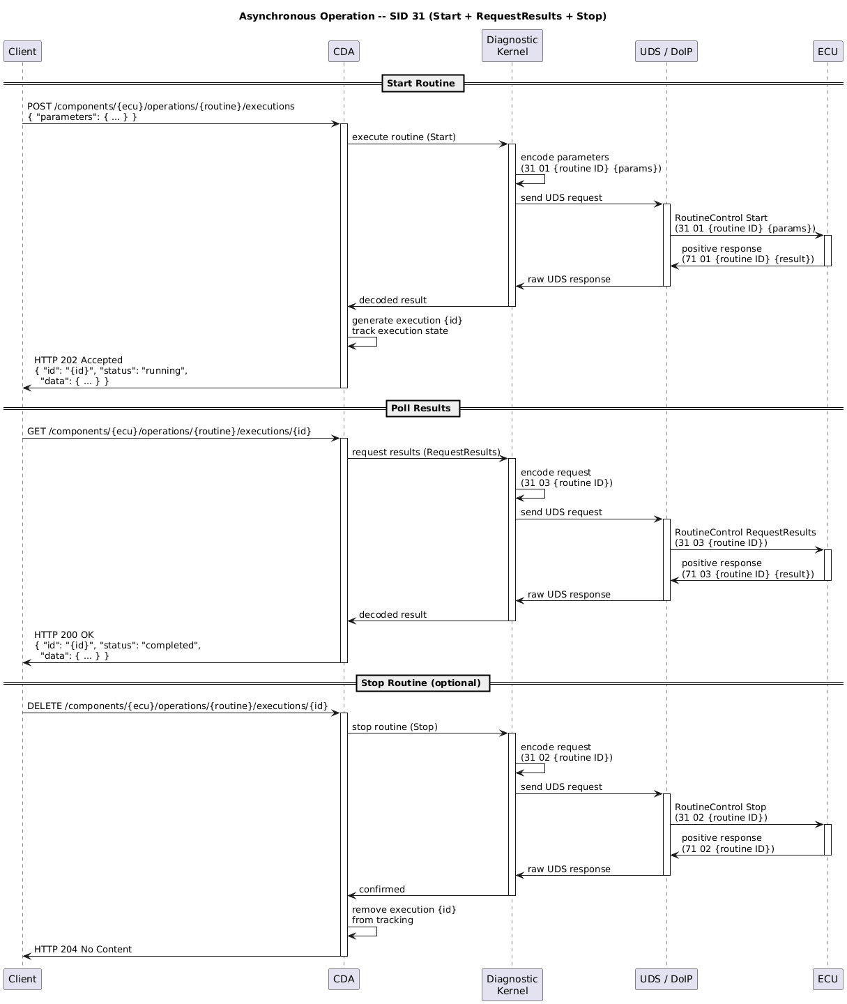
Operations in the CDA are Routines (3116), Reset (1116), and an extension to configure communication parameters (Communication Parameters (ComParams)). Reset – SID 1116 For compatibility with SOVD version 1.0 and earlier, the operations Routines – SID 3116 All services with the SID 3116 are considered for operations – as with data, their short names are
preprocessed by removing configurable prefixes/suffixes to determine routine identifiers available as
the The items in the list of items available under
Synchronous – Start only When a routine only defines the
Note Operations without a Asynchronous – Stop and/or RequestResults When a routine has The POST request returns HTTP status Additionally, by calling Subfunction Requirements If any of the required subfunctions are not available in the diagnostic database, the call will result in an error:
These requirements can be bypassed using the Force Parameter If DELETE is called and an ECU error is encountered, the When
Stop Response Data When a Stop subfunction returns non-empty response data, the DELETE endpoint returns HTTP status
Note This is an extension to the standard to support Stop operations that return response data. Rationale for POST Response Data When executing an asynchronous function, there’s no good way to return the response of the routine with the GET to the id-endpoint, since that endpoint should only return the status of the RequestResults call. Therefore, the response of the routine is returned directly when executing the routine with POST in addition to the id. Note This is a deviation from the standard, but is required to allow clients to handle routine responses properly. |
3.3.4.1. IOControl – SID 2A16
Note
Not supported at this time
3.3.5. Modes
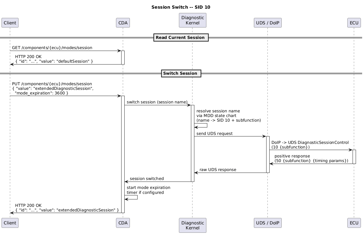
3.3.5.1. Session – SID 1016
The endpoint
The format for the request body is: {
"value": "<session name>",
"mode_expiration": 3600
}
The names of the sessions for the field The field In the response body, See also chapter 7.16 in ISO 17978-3.
|
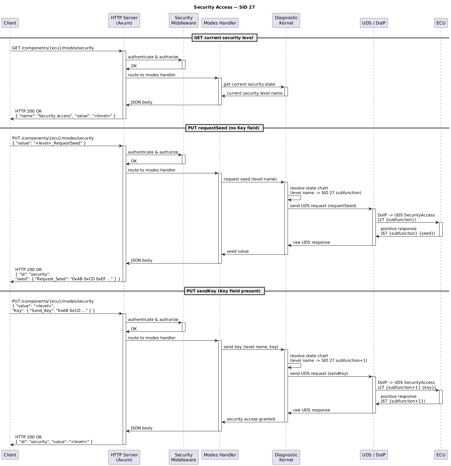
3.3.5.2. Security – SID 2716
The endpoints are available under the path Works similarly to Session defined in the previous chapter. The names of the security access levels are determined through the state charts for the SID 2716 services. RequestSeed flow A client initiates security access by sending a
Example values and their parsed components:
RequestSeed service name resolution The CDA resolves the UDS RequestSeed service (SID 2716) by searching all SID 2716 services in the ISO 14229-1 RequestSeed subfunction range (odd subfunctions 1, 3-5, 7-41, exactly 2 request parameters) and selecting the first whose short name contains the level name (underscores stripped, case-insensitive). This requires the level name to be embedded in the service short name, which both supported naming conventions satisfy:
|
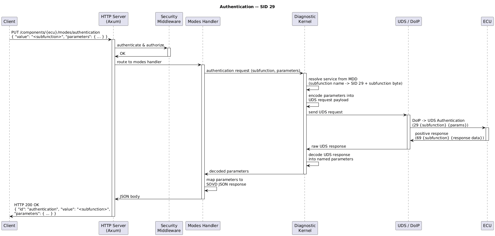
3.3.5.3. Authentication – SID 2916
Note This is technically a deviation from Table 343 in the ISO API. The table in the ISO is misleading, since 8.3.2 and 8.3.3 describe them separately. The endpoints are available under Diagnostic data descriptions have to specify the used services including the subfunction individually, so the request parameters can be converted into UDS payloads.
|
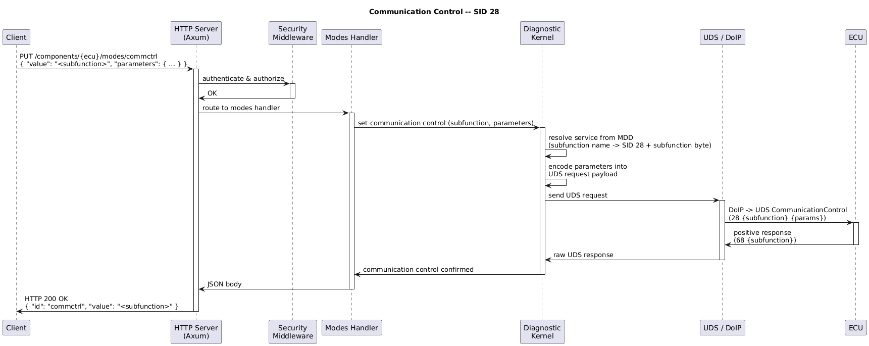
3.3.5.4. Communication Control – SID 2816
To control the communication parameters of an ECU, the path The attribute
Matching 2816 service entries must be present in the diagnostic description. Parameters can be provided
through an additional Note Other values are not supported.
|
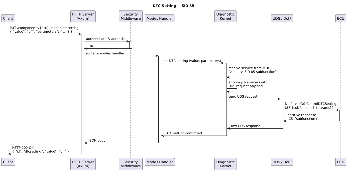
3.3.5.5. DTC Setting – SID 8516
To control the DTC settings of an ECU, the path The attribute Matching 8516 service entries must be present in the diagnostic description. Parameters can be provided
through an additional Note Other specific extensions to the values are not supported.
|
3.3.6. Faults – SID 1416 & 1916
The following operations must be implemented:
The query parameter Available keys:
All values are either boolean values (true/false), or a bit value (0/1). Additionally, a special key called
|
![' SPDX-FileCopyrightText: 2026 Copyright (c) Contributors to the Eclipse Foundation
'
' See the NOTICE file(s) distributed with this work for additional
' information regarding copyright ownership.
'
' This program and the accompanying materials are made available under the
' terms of the Apache License Version 2.0 which is available at
' https://www.apache.org/licenses/LICENSE-2.0
'
' SPDX-License-Identifier: Apache-2.0
@startuml
title Fault Read -- SID 19
participant Client
participant CDA
participant "Diagnostic\nKernel" as DIAG
participant "UDS / DoIP" as COMM
participant ECU
== List All Faults ==
Client -> CDA : GET /components/{ecu}/faults\n?status[confirmedDtc]=true
activate CDA
CDA -> DIAG : read DTCs (status mask)
activate DIAG
DIAG -> DIAG : build status mask byte\nfrom query parameters
DIAG -> COMM : send UDS request
activate COMM
COMM -> ECU : DoIP -> UDS ReadDTCInformation\n(19 02 {status mask})
activate ECU
ECU -> COMM : positive response\n(59 02 {availability mask} {DTC records})
deactivate ECU
COMM -> DIAG : raw UDS response
deactivate COMM
DIAG -> DIAG : parse DTC records\n(DTC number + status byte)
DIAG -> CDA : list of DTCs with status
deactivate DIAG
CDA -> CDA : map DTCs to SOVD\nfault representation
CDA -> Client : HTTP 200 OK\n{ "items": [ { "id": "...", "status": { ... } }, ... ] }
deactivate CDA
== Read Single Fault with Extended Data ==
Client -> CDA : GET /components/{ecu}/faults/{dtc}\n?include-extended-data=true&include-snapshot=true
activate CDA
CDA -> DIAG : read DTC detail + extended + snapshot
activate DIAG
DIAG -> COMM : send UDS request(s)
activate COMM
COMM -> ECU : ReadDTCInformation\n(19 04/06 {DTC} ...)
activate ECU
ECU -> COMM : positive response(s)\nwith snapshot & extended data
deactivate ECU
COMM -> DIAG : raw UDS response(s)
deactivate COMM
DIAG -> DIAG : decode snapshot &\nextended data records
DIAG -> CDA : DTC detail with environment data
deactivate DIAG
CDA -> Client : HTTP 200 OK\n{ "id": "...", "status": { ... },\n "environment_data": { ... } }
deactivate CDA
@enduml](../_images/plantuml-96d32b7774fab847742cdb402b17b3bab1898b1e.png)
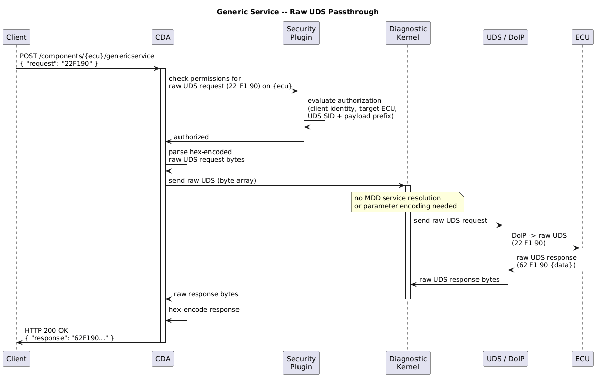
3.3.7. Generic Service
The The client sends a hex-encoded UDS request in the JSON body, and receives the raw hex-encoded UDS response from the ECU. Permissions for generic service calls can be checked and enforced through the security plugin. Since
generic service requests bypass the structured service resolution, the security plugin receives the
raw UDS request payload (e.g.
|
3.3.8. Version Endpoint
Software Architecture: API Version Endpoint Registration Function arch~sovd-api-version-registration-function
|
The CDA provides a version registration function that sets up version-related endpoints during initialization. Registration Function The function accepts the following parameters: It always registers the standard The fields Standard Endpoint: /version-info The {
"sovd_info": [
{
"version": "<sovd_api_version>",
"base_uri": "<relative uri-reference to base of sovd_api_version>",
"vendor_info": {
"name": "<vendor_name>",
"version": "<implementation_version>",
"commit": "<commit>",
"build_date": "<build_date>"
}
}
]
}
Optional Vendor-Specific Endpoints: /data/version, /apps/sovd2uds/data/version When enabled, these endpoints are registered as static data endpoints returning: {
"id": "version",
"data": {
"name": "<vendor_name>",
"api": {
"version": "<api_version>"
},
"implementation": {
"version": "<implementation_version>",
"commit": "<commit>",
"build_date": "<build_date>"
}
}
}
Both endpoint types are available immediately after the HTTP server starts and do not require any ECU communication.
Note The current implementation only registers |
![' SPDX-FileCopyrightText: 2026 Copyright (c) Contributors to the Eclipse Foundation
'
' See the NOTICE file(s) distributed with this work for additional
' information regarding copyright ownership.
'
' This program and the accompanying materials are made available under the
' terms of the Apache License Version 2.0 which is available at
' https://www.apache.org/licenses/LICENSE-2.0
'
' SPDX-License-Identifier: Apache-2.0
@startuml
title Version Registration Function
participant "Application\nStartup" as APP
participant "Version\nRegistration\nFunction" as VREG
participant "HTTP Server\n(Axum)" as HTTP
APP -> VREG : register_version_endpoints(\nvendor_name, implementation_version,\ncommit, build_date)
activate VREG
VREG -> VREG : determine base_uri\nand api_version
VREG -> HTTP : register GET /version-info
activate HTTP
HTTP -> VREG : registered
deactivate HTTP
alt optional vendor-specific endpoints enabled
VREG -> HTTP : register GET /data/version
activate HTTP
HTTP -> VREG : registered
deactivate HTTP
VREG -> HTTP : register GET /apps/sovd2uds/data/version
activate HTTP
HTTP -> VREG : registered
deactivate HTTP
end
VREG -> APP : registration complete
deactivate VREG
== Runtime: Client requests version info ==
participant Client
Client -> HTTP : GET /version-info
activate HTTP
HTTP -> Client : HTTP 200 OK\n{ "sovd_info": [ { "version": "...",\n"base_uri": "...", "vendor_info": { ... } } ] }
deactivate HTTP
@enduml](../_images/plantuml-7feeadac5180585ff4e111c2da668589046a154d.png)
3.3.9. Error Codes & Messages
Note
todo define
3.4. Extensions to ISO standard API
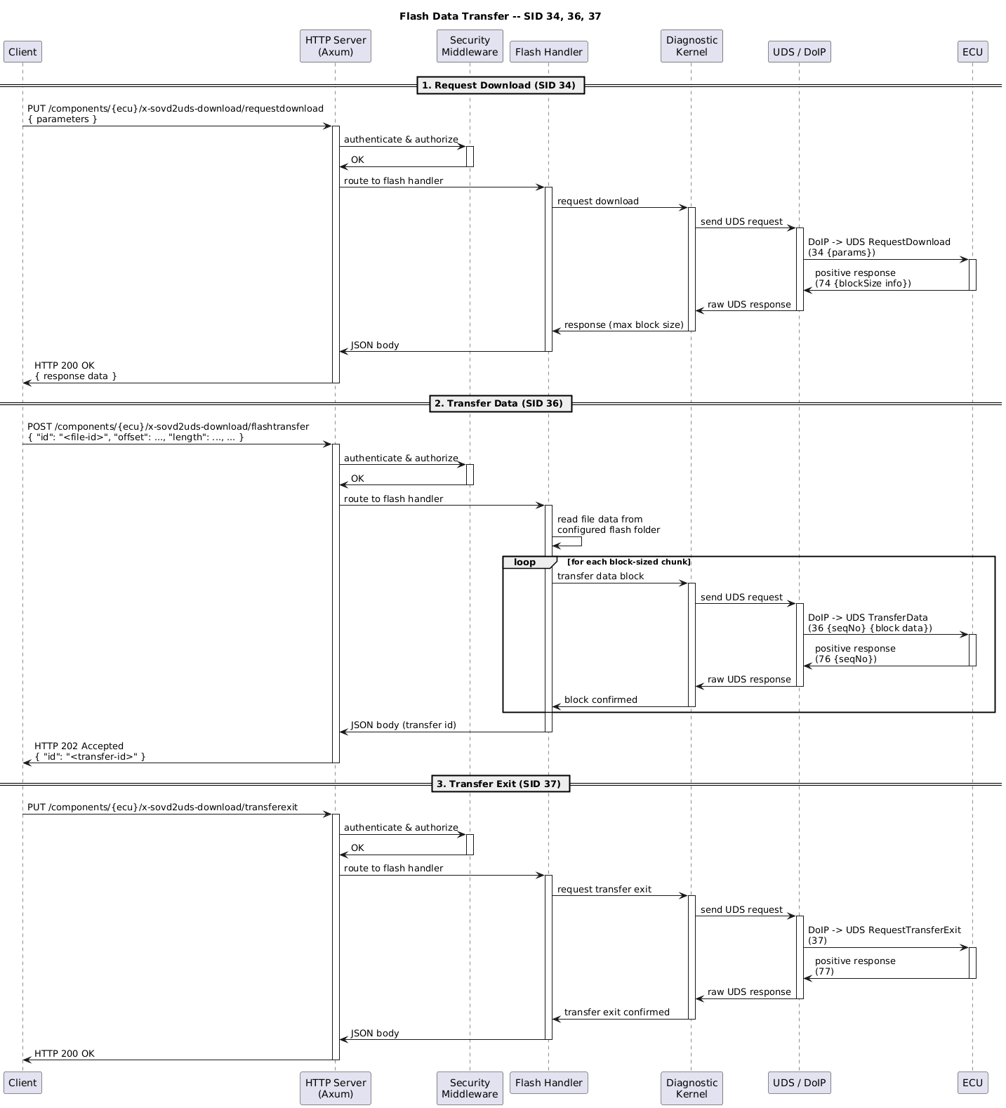
3.4.1. Flash-API
3.4.1.1. Introduction
Flashing via UDS generally follows the following sequence. OEMs might choose to call additional services or modify the sequence.
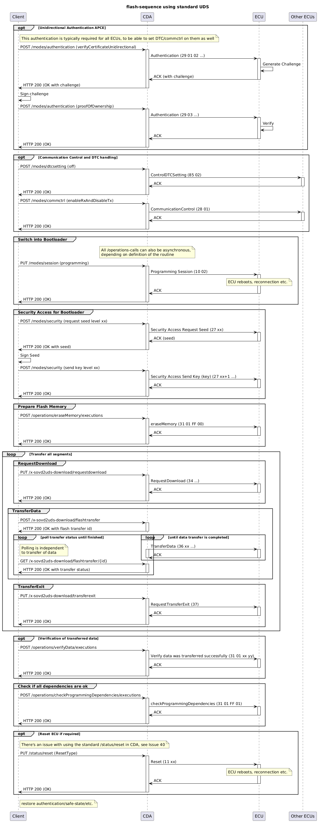
To allow the flashing functionality shown above, the SOVD-API from ISO 17978-3 needs to be extended with the functionality defined in this document.
The standard doesn’t define how the required services should be mapped in the Classic Diagnostic Adapter.
3.4.1.2. API
Motivation To flash an ECU, the CDA needs to have access to the files that should be flashed. This API allows listing the files that are available for flashing. Endpoints
|
![' SPDX-FileCopyrightText: 2026 Copyright (c) Contributors to the Eclipse Foundation
'
' See the NOTICE file(s) distributed with this work for additional
' information regarding copyright ownership.
'
' This program and the accompanying materials are made available under the
' terms of the Apache License Version 2.0 which is available at
' https://www.apache.org/licenses/LICENSE-2.0
'
' SPDX-License-Identifier: Apache-2.0
@startuml
title Flash File Management
participant Client
participant "HTTP Server\n(Axum)" as HTTP
participant "Security\nMiddleware" as SEC
participant "Flash Handler" as HANDLER
participant "File System" as FS
Client -> HTTP : GET /apps/sovd2uds/bulk-data/flashfiles
activate HTTP
HTTP -> SEC : authenticate & authorize
activate SEC
SEC -> HTTP : OK
deactivate SEC
HTTP -> HANDLER : route to flash handler
activate HANDLER
HANDLER -> FS : list configured flash folder\n(recursive)
activate FS
FS -> HANDLER : list of files and metadata
deactivate FS
HANDLER -> HANDLER : build response with\nfile entries
HANDLER -> HTTP : JSON body
deactivate HANDLER
HTTP -> Client : HTTP 200 OK\n{ "items": [ { "id": "...", "name": "...", ... }, ... ] }
deactivate HTTP
@enduml](../_images/plantuml-49a665144e60d4b249e0771380318c7347d24dbc.png)
Motivation To flash an ECU, the CDA needs to be able to transfer the flash data to the ECU. This API allows transferring the data in block-sized chunks, as required by UDS. Endpoints All paths are prefixed with
|
3.4.1.3. Configuration
Motivation The CDA needs to know where to find the files that should be flashed to the ECUs. This configuration allows setting the flash folder. Configuration Parameter The following configuration parameter must be available in the CDA configuration:
|
3.4.2. Functional communication
Software Architecture: Diagnostic description & Configuration arch~sovd-api-functional-communication-dd-configuration
|
Information about the available functional groups, the available services in those groups, and their communication parameters must be provided in a separate diagnostic description. The diagnostic description’s MDD filename, in which the information for functional communication is contained, must be configurable. When no file is configured, functional communication is not available. A configuration option in the CDA can further filter the available functional groups from the diagnostic description. Rationale Extracting a standardized resource collection for functional communication from individual ECU descriptions is challenging and non-transparent when extracting common functional services from all ECU files. Therefore, we chose to do this via a separate diagnostic description file. This also follows the general pattern of one MDD file to an available standardized resource collection. |
3.4.2.1. API
Functional group functionality - if available - must be available in the Within that path, a standardized resource collection (chapter 5.4.2 in ISO/DIS 17978-3) must be available, with the linked semantics.
|
![' SPDX-FileCopyrightText: 2026 Copyright (c) Contributors to the Eclipse Foundation
'
' See the NOTICE file(s) distributed with this work for additional
' information regarding copyright ownership.
'
' This program and the accompanying materials are made available under the
' terms of the Apache License Version 2.0 which is available at
' https://www.apache.org/licenses/LICENSE-2.0
'
' SPDX-License-Identifier: Apache-2.0
@startuml
title Functional Communication API -- Overview
participant Client
participant "HTTP Server\n(Axum)" as HTTP
participant "Security\nMiddleware" as SEC
participant "Functional\nComm Handler" as HANDLER
participant "Diagnostic\nKernel" as DIAG
Client -> HTTP : GET /functions/functionalgroups
activate HTTP
HTTP -> SEC : authenticate & authorize
activate SEC
SEC -> HTTP : OK
deactivate SEC
HTTP -> HANDLER : route to functional comm handler
activate HANDLER
HANDLER -> DIAG : list functional groups\n(from dedicated MDD file)
activate DIAG
DIAG -> HANDLER : available functional groups
deactivate DIAG
HANDLER -> HTTP : JSON body
deactivate HANDLER
HTTP -> Client : HTTP 200 OK\n{ "items": [ { "id": "<group-name>", ... }, ... ] }
deactivate HTTP
@enduml](../_images/plantuml-7079fd9f8d0bb5f5367ad378df97f947ff5eea64.png)
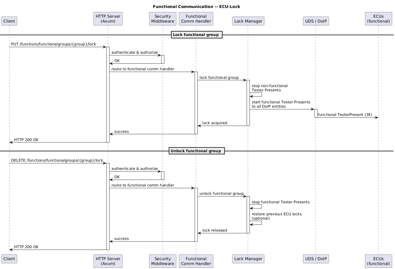
Software Architecture: Functional Communication ECU-Lock behavior arch~sovd-api-functional-communication-locks
|
Locking a functional group will start sending functional Tester Presents to the functional DoIP addresses of all DoIP Entities, and stop sending non-functional Tester Presents. Lock Options There can be an option to restore the previous ECU locks (and their Tester Presents).
|
Data Since functional communication returns data from multiple ECUs, the In case of errors, the Note The content-type
|
![' SPDX-FileCopyrightText: 2026 Copyright (c) Contributors to the Eclipse Foundation
'
' See the NOTICE file(s) distributed with this work for additional
' information regarding copyright ownership.
'
' This program and the accompanying materials are made available under the
' terms of the Apache License Version 2.0 which is available at
' https://www.apache.org/licenses/LICENSE-2.0
'
' SPDX-License-Identifier: Apache-2.0
@startuml
title Functional Communication -- Data Read
participant Client
participant "HTTP Server\n(Axum)" as HTTP
participant "Security\nMiddleware" as SEC
participant "Functional\nComm Handler" as HANDLER
participant "Diagnostic\nKernel" as DIAG
participant "UDS / DoIP" as COMM
participant "ECUs\n(functional)" as ECUS
Client -> HTTP : GET /functions/functionalgroups/{group}/data/{id}
activate HTTP
HTTP -> SEC : authenticate & authorize
activate SEC
SEC -> HTTP : OK
deactivate SEC
HTTP -> HANDLER : route to functional comm handler
activate HANDLER
HANDLER -> DIAG : read data (functional, service name)
activate DIAG
DIAG -> DIAG : resolve service from MDD\n(short name -> SID 22 + DID)
DIAG -> COMM : send functional UDS request
activate COMM
COMM -> ECUS : DoIP (functional) -> UDS\nReadDataByIdentifier (22 {DID})
activate ECUS
ECUS -> COMM : responses from ECUs\n(62 {DID} {data})
deactivate ECUS
COMM -> DIAG : responses from all ECUs
deactivate COMM
DIAG -> DIAG : decode each ECU response\ninto named parameters
DIAG -> HANDLER : decoded parameters per ECU
deactivate DIAG
HANDLER -> HANDLER : map to SOVD JSON response\nwith ECU name as key in "data"
HANDLER -> HTTP : JSON body
deactivate HANDLER
HTTP -> Client : HTTP 200 OK\n{ "id": "...", "data": {\n "ecu1": { ... },\n "ecu2": { ... }\n}, "errors": [ ... ] }
deactivate HTTP
@enduml](../_images/plantuml-9e691512890bdea062c49ee89d3a1b24a08ae260.png)
Software Architecture: Functional Communication - Operations arch~sovd-api-functional-communication-operations
|
Same principle as with data, except that the top-level element name is Note The content-type
|
![' SPDX-FileCopyrightText: 2026 Copyright (c) Contributors to the Eclipse Foundation
'
' See the NOTICE file(s) distributed with this work for additional
' information regarding copyright ownership.
'
' This program and the accompanying materials are made available under the
' terms of the Apache License Version 2.0 which is available at
' https://www.apache.org/licenses/LICENSE-2.0
'
' SPDX-License-Identifier: Apache-2.0
@startuml
title Functional Communication -- Operations
participant Client
participant "HTTP Server\n(Axum)" as HTTP
participant "Security\nMiddleware" as SEC
participant "Functional\nComm Handler" as HANDLER
participant "Diagnostic\nKernel" as DIAG
participant "UDS / DoIP" as COMM
participant "ECUs\n(functional)" as ECUS
Client -> HTTP : POST /functions/functionalgroups/{group}/operations/{id}/executions\n{ "parameters": { ... } }
activate HTTP
HTTP -> SEC : authenticate & authorize
activate SEC
SEC -> HTTP : OK
deactivate SEC
HTTP -> HANDLER : route to functional comm handler
activate HANDLER
HANDLER -> DIAG : execute operation (functional, service name, parameters)
activate DIAG
DIAG -> DIAG : resolve service from MDD\n(short name -> SID 31 + routine ID)
DIAG -> DIAG : encode parameters into\nUDS request payload
DIAG -> COMM : send functional UDS request
activate COMM
COMM -> ECUS : DoIP (functional) -> UDS\nRoutineControl (31 01 {RID} {params})
activate ECUS
ECUS -> COMM : responses from ECUs\n(71 01 {RID} {data})
deactivate ECUS
COMM -> DIAG : responses from all ECUs
deactivate COMM
DIAG -> DIAG : decode each ECU response\ninto named parameters
DIAG -> HANDLER : decoded parameters per ECU
deactivate DIAG
HANDLER -> HANDLER : map to SOVD JSON response\nwith ECU name as key in "parameters"
HANDLER -> HTTP : JSON body
deactivate HANDLER
HTTP -> Client : HTTP 200 OK\n{ "parameters": {\n "ecu1": { ... },\n "ecu2": { ... }\n}, "errors": [ ... ] }
deactivate HTTP
@enduml](../_images/plantuml-7d7b45f818837bf62d5a22c4b08edd092c536af6.png)
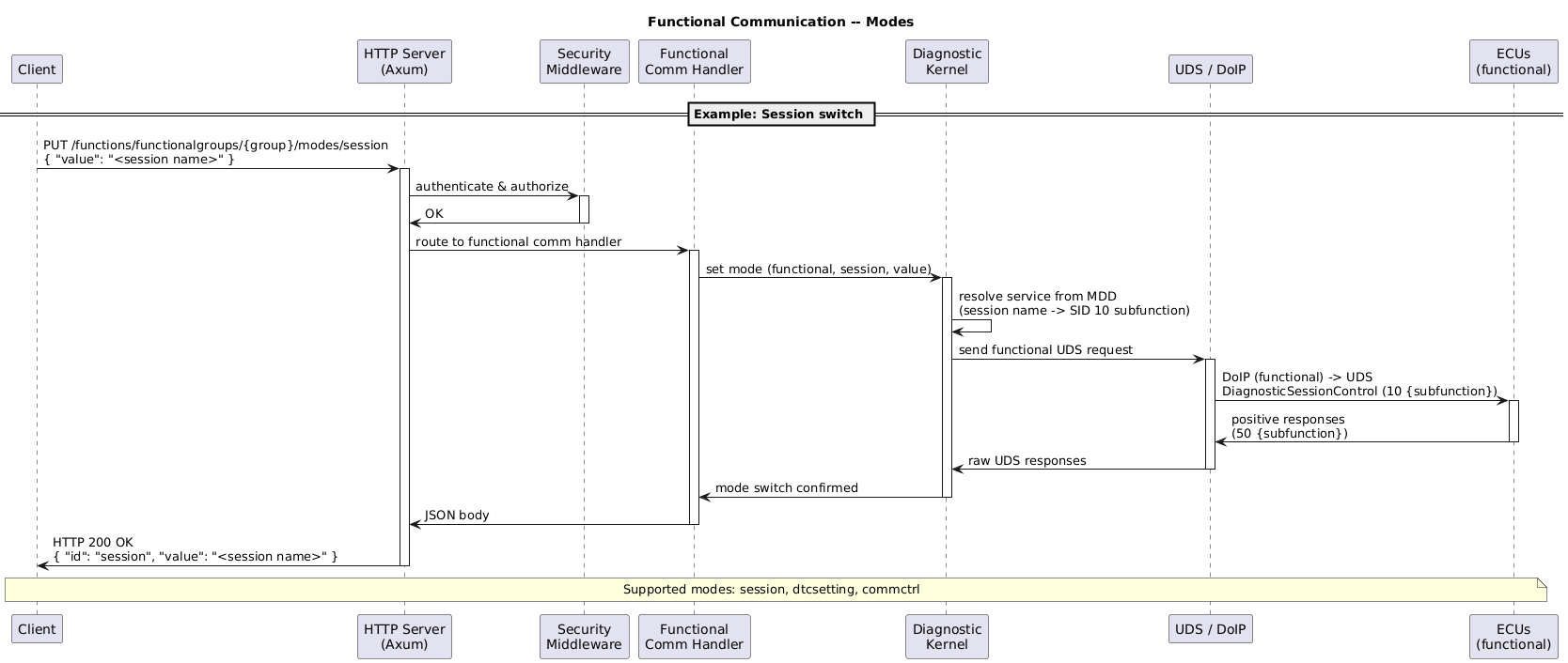
Software Architecture: Functional Communication - Modes arch~sovd-api-functional-communication-modes
|
The following modes must be supported for functional groups when the underlying diagnostic description contains them:
|
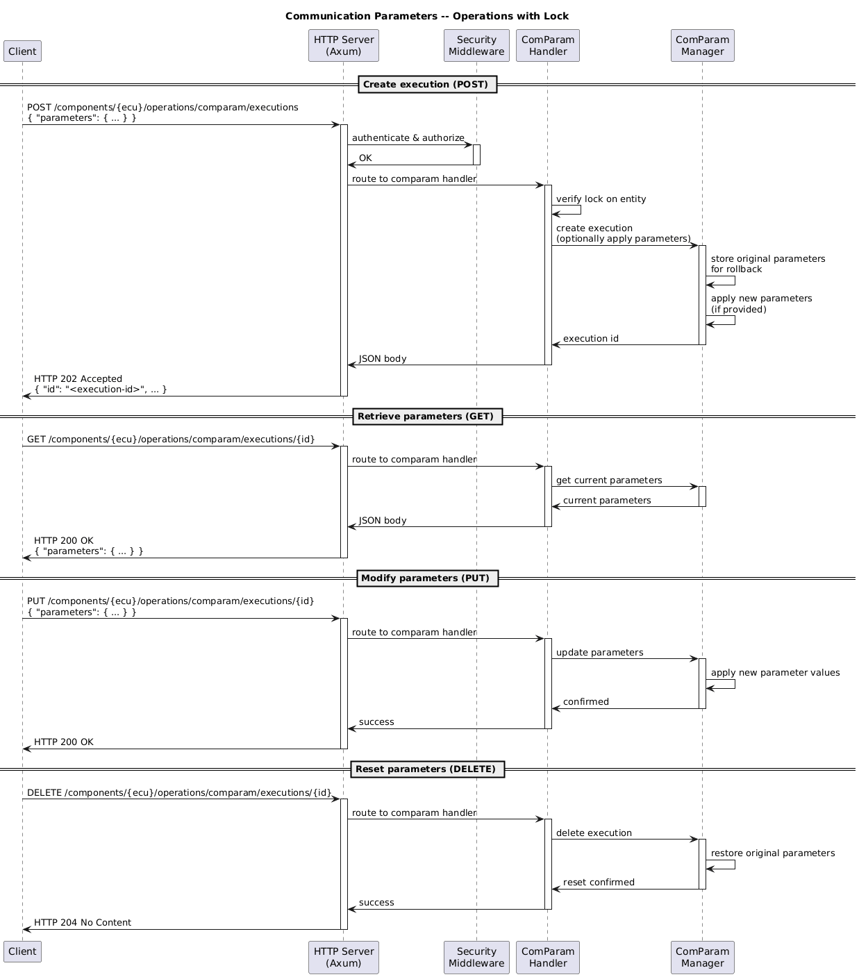
3.4.3. Communication Parameters (ComParams)
Note Communication parameter handling is exposed through a Motivation When using the CDA to communicate with classic ECUs, a client needs the ability to modify the communication parameters like timeouts and retries on-the-fly. This API provides a way to do this. Retrieving & Modifying with a lock
These operations require a lock on the entity. Only one execution of communication parameters per entity is allowed.
|
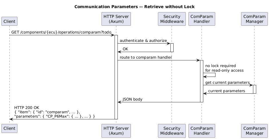
Software Architecture: Retrieve Communication Parameters without Lock arch~sovd-api-comparams-without-lock
|
Note This is a small extension to the ISO standard To allow retrieving the communication parameters without a lock, a GET on Rationale Clients without a lock might want to log the current communication parameters for informational purposes, so they should be able to retrieve them. Handling this with the POST/GET semantic with only a single execution would make the handling extremely complicated for parallel clients with & without locks.
Example for directly retrieving communication parameters: {
"item": {
"id": "comparam",
"name": "Communication parameters",
"asynchronous_execution": true,
"proximity_proof_required": false
},
"parameters": {
"CP_P6Max": {
"value": "4500000",
"unit": {
"factor_to_si_unit": 1e-06
}
},
"CP_RC78Handling": {
"value": "Continue until RC78 timeout"
},
"...": {
"...": "..."
}
}
}
|
3.4.4. MDD Embedded Files API
Note This is a SOVD-API extension. Motivation When an additional private SOVD-Server is tasked with providing functionality that replaces classic offboard-tester
functionality, additional data from the single-ecu-jobs embedded in the original The odx-converter offers an option to include code-files from the pdx, as well as partial contents from those files. This API allows the retrieval of these files. Embedded Content Retrieval The API to retrieve embedded files utilizes a bulk-data endpoint, as defined in Bulk Data Endpoints within
Other methods are not allowed (e.g. data can’t be modified), and will return an HTTP 405 error code.
|
![' SPDX-FileCopyrightText: 2026 Copyright (c) Contributors to the Eclipse Foundation
'
' See the NOTICE file(s) distributed with this work for additional
' information regarding copyright ownership.
'
' This program and the accompanying materials are made available under the
' terms of the Apache License Version 2.0 which is available at
' https://www.apache.org/licenses/LICENSE-2.0
'
' SPDX-License-Identifier: Apache-2.0
@startuml
title MDD Embedded Files
participant Client
participant "HTTP Server\n(Axum)" as HTTP
participant "Security\nMiddleware" as SEC
participant "Embedded Files\nHandler" as HANDLER
participant "Diagnostic\nKernel" as DIAG
== List embedded files ==
Client -> HTTP : GET /components/{ecu}/x-sovd2uds-bulk-data/mdd-embedded-files
activate HTTP
HTTP -> SEC : authenticate & authorize
activate SEC
SEC -> HTTP : OK
deactivate SEC
HTTP -> HANDLER : route to embedded files handler
activate HANDLER
HANDLER -> DIAG : list embedded files (variant)
activate DIAG
DIAG -> DIAG : read file metadata\nfrom MDD
DIAG -> HANDLER : list of file entries with metadata
deactivate DIAG
HANDLER -> HTTP : JSON body
deactivate HANDLER
HTTP -> Client : HTTP 200 OK\n{ "items": [ { "id": "...", ... }, ... ] }
deactivate HTTP
== Download embedded file ==
Client -> HTTP : GET /components/{ecu}/x-sovd2uds-bulk-data/mdd-embedded-files/{id}
activate HTTP
HTTP -> SEC : authenticate & authorize
activate SEC
SEC -> HTTP : OK
deactivate SEC
HTTP -> HANDLER : route to embedded files handler
activate HANDLER
HANDLER -> DIAG : get embedded file data (id, variant)
activate DIAG
DIAG -> DIAG : extract file content\nfrom MDD
DIAG -> HANDLER : binary file data
deactivate DIAG
HANDLER -> HTTP : binary response
deactivate HANDLER
HTTP -> Client : HTTP 200 OK\nContent-Type: <mime-type>\n<binary data>
deactivate HTTP
@enduml](../_images/plantuml-6e0d2d58618bf2fa8144556f5064b8e3ae75bb5e.png)
3.4.5. Single ECU Jobs
Motivation When a client wants to replace the classical single-ecu-jobs defined in the odx description, it could need the original input/output parameters from those jobs. This API provides access to the data for the single-ecu-jobs, which were present in the original odx at the time of conversion. Retrieving data Note The available data may depend on the currently detected variant, since the ecu jobs are defined for variants. The following paths will be available within the
Read the Single ECU Jobs OpenAPI specification for details:
|
![' SPDX-FileCopyrightText: 2026 Copyright (c) Contributors to the Eclipse Foundation
'
' See the NOTICE file(s) distributed with this work for additional
' information regarding copyright ownership.
'
' This program and the accompanying materials are made available under the
' terms of the Apache License Version 2.0 which is available at
' https://www.apache.org/licenses/LICENSE-2.0
'
' SPDX-License-Identifier: Apache-2.0
@startuml
title Single ECU Jobs
participant Client
participant "HTTP Server\n(Axum)" as HTTP
participant "Security\nMiddleware" as SEC
participant "Single ECU Jobs\nHandler" as HANDLER
participant "Diagnostic\nKernel" as DIAG
== List single ECU jobs ==
Client -> HTTP : GET /components/{ecu}/x-single-ecu-jobs
activate HTTP
HTTP -> SEC : authenticate & authorize
activate SEC
SEC -> HTTP : OK
deactivate SEC
HTTP -> HANDLER : route to single ECU jobs handler
activate HANDLER
HANDLER -> DIAG : list single ECU jobs (variant)
activate DIAG
DIAG -> DIAG : read job definitions\nfrom MDD (variant-dependent)
DIAG -> HANDLER : list of job items
deactivate DIAG
HANDLER -> HTTP : JSON body
deactivate HANDLER
HTTP -> Client : HTTP 200 OK\n{ "items": [ { "id": "...", ... }, ... ] }
deactivate HTTP
== Read single ECU job data ==
Client -> HTTP : GET /components/{ecu}/x-single-ecu-jobs/{id}
activate HTTP
HTTP -> SEC : authenticate & authorize
activate SEC
SEC -> HTTP : OK
deactivate SEC
HTTP -> HANDLER : route to single ECU jobs handler
activate HANDLER
HANDLER -> DIAG : get job data (id, variant)
activate DIAG
DIAG -> DIAG : read job input/output\nparameters from MDD
DIAG -> HANDLER : job data (parameters, metadata)
deactivate DIAG
HANDLER -> HTTP : JSON body
deactivate HANDLER
HTTP -> Client : HTTP 200 OK\n{ "id": "...", "data": { ... } }
deactivate HTTP
@enduml](../_images/plantuml-062956fb7f741e6142b260c8e3002223871f4e88.png)
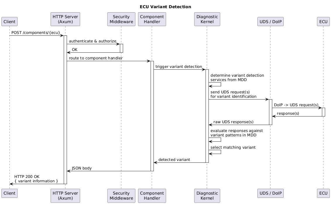
3.4.6. ECU Variant Detection
Motivation Some ECUs have different variants, which support different functionality. To provide the correct functionality, the CDA needs to be able to detect the variant in use. This variant may change at any point due to the nature of the ECUs software. Clients may need to trigger this explicitly to ensure correct functionality. Variant Detection Trigger A PUT on the path
|
3.5. Communication
3.5.1. DoIP Communication
DoIP Communication is described in the ISO 13400 standard. The CDA implements DoIP as transport layer for UDS diagnostic communication with vehicle ECUs.
The communication parameters depend on the logical link used for the communication, filtered by configuration and actual ECU detection/availability.
3.5.1.1. Protocol Versions
The CDA supports multiple DoIP protocol versions as defined in ISO 13400-2. The protocol version is included in the DoIP header of every message to indicate which version of the standard the message conforms to. Supported Versions
Version Selection The protocol version is configurable. The default version is ISO 13400-2:2012 ( |
3.5.1.2. Message Framing
All DoIP messages share a common 8-byte header followed by a variable-length payload. The codec layer is responsible for encoding outgoing messages and decoding incoming messages from the byte stream. Header Structure
Supported Payload Types
Decoding Behavior The decoder reads the 8-byte header first. If insufficient data is available, it waits for more data to arrive on the stream. Once the header is complete, it reads the number of bytes indicated by the payload length field and dispatches to the appropriate payload parser based on the payload type. |
3.5.1.3. Communication Parameters
The DoIP communication layer is parameterized through a set of communication parameters (COM parameters) that control addressing, timeouts, and retry behavior. These parameters are sourced from the diagnostic database (MDD files) and can vary per logical link.
Note When these parameters are sourced from MDD files, multiple files could define different values for the same logical address due to duplicated logical addresses. |
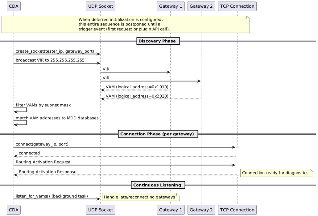
3.5.1.4. Vehicle Identification
Vehicle identification is the process by which the CDA discovers DoIP entities on the network. It uses UDP broadcast to solicit Vehicle Announcement Messages from all reachable DoIP entities. Discovery Process
Vehicle Announcement Message Content Each VAM contains:
Spontaneous VAM Listener After initial discovery, a background task continuously listens on the gateway port for spontaneous VAM broadcasts. This handles:
When a new or known VAM is received, the system establishes or re-uses the connection and triggers variant detection for the associated ECUs.
Vehicle Identification Sequence¶ |
![@startuml
skinparam backgroundColor #FFFFFF
skinparam sequenceArrowThickness 2
participant "CDA" as CDA
participant "UDP Socket\n(port 13400)" as UDP
participant "DoIP Entity A" as GWA
participant "DoIP Entity B" as GWB
== Initial Discovery ==
CDA -> UDP: Create socket\n(broadcast, address reuse)
CDA -> UDP: VIR broadcast to\n255.255.255.255:13400
UDP -> GWA: Vehicle Identification\nRequest (0x0001)
UDP -> GWB: Vehicle Identification\nRequest (0x0001)
GWA --> UDP: VAM (0x0004)\n[logical_addr, VIN, EID, GID]
GWB --> UDP: VAM (0x0004)\n[logical_addr, VIN, EID, GID]
CDA -> CDA: Filter VAMs by\nsubnet mask
CDA -> CDA: Match logical addresses\nto MDD databases
== Spontaneous Listener (background) ==
CDA -> UDP: Listen for spontaneous VAMs
...
GWA --> UDP: Spontaneous VAM\n(entity came online)
UDP --> CDA: New VAM received
CDA -> CDA: Establish connection\nand trigger variant detection
@enduml](../_images/plantuml-43af20074db3ee7444a90aeed8cba1dd843e394b.png)
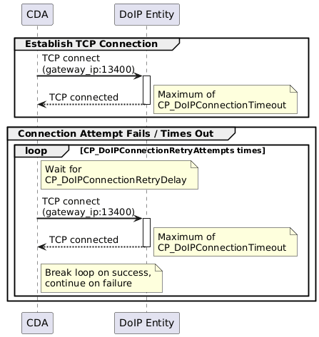
3.5.1.5. Connection Establishment
After a DoIP entity is discovered via vehicle identification, a TCP connection is established to enable diagnostic communication. TCP Connection A TCP connection is initiated to the discovered gateway IP address on the configured
gateway port (default: 13400). The connection attempt is bounded by the
Retry Behavior If the initial connection attempt fails or times out, the system retries according to:
If the connection was initiated as part of a diagnostic request, a timeout error is reported to the caller.
DoIP Connection Establishment¶ |
3.5.1.6. Routing Activation
After establishing a TCP connection, routing activation must be performed before diagnostic messages can be exchanged. This registers the tester’s logical address with the DoIP entity. Request The CDA sends a Routing Activation Request (payload type
Response Handling The response contains an activation code that determines the outcome:
The routing activation response must be received within
Routing Activation Sequence¶ |
![@startuml
skinparam backgroundColor #FFFFFF
skinparam sequenceArrowThickness 2
participant "CDA" as CDA
participant "DoIP Entity" as ECU
== Routing Activation ==
CDA -> ECU: Routing Activation Request (0x0005)\n[tester_addr, type=Default]
activate ECU
note right: Maximum of\nCP_DoIPRoutingActivationTimeout
alt Activation Successful (0x10)
ECU --> CDA: Routing Activation Response\n[code=SuccessfullyActivated]
deactivate ECU
note right of CDA: Connection ready\nfor diagnostics
else TLS Required (0x07)
ECU --> CDA: Routing Activation Response\n[code=DeniedEncryptedTLSRequired]
deactivate ECU
CDA -> CDA: Close plain TCP connection
CDA -> ECU: TCP connect to TLS port (3496)
activate ECU
CDA <-> ECU: TLS Handshake
CDA -> ECU: Routing Activation Request (0x0005)\n[tester_addr, type=Default]
ECU --> CDA: Routing Activation Response\n[code=SuccessfullyActivated]
deactivate ECU
note right of CDA: TLS connection ready\nfor diagnostics
else Denied (any other code)
ECU --> CDA: Routing Activation Response\n[code=Denied*]
deactivate ECU
note right of CDA: Report routing error
end
@enduml](../_images/plantuml-34027d1e8f9fca283132a3772f8834e5e24ea0d5.png)
3.5.1.7. TLS Connection Support
The CDA supports TLS-secured DoIP connections as defined in ISO 13400. TLS is activated as a fallback when a DoIP entity requires encrypted communication. TLS Activation Trigger TLS is not used by default. It is activated when a Routing Activation Response
returns the code
TLS Configuration
|
3.5.1.8. Diagnostic Message Exchange
Diagnostic messages carry UDS (Unified Diagnostic Services) data between the CDA and ECUs through the DoIP transport layer. Sending a Diagnostic Message
ACK/NACK Handling After sending, the CDA waits for an acknowledgement within
Receiving the Diagnostic Response After a successful ACK, the CDA waits for the diagnostic response. Multiple intermediate responses may be received before the final response:
Functional Addressing For functional group communication, a single diagnostic message is sent to the
gateway using the functional address ( Auto-ACK on Receive When the CDA receives a diagnostic message from a DoIP entity, it automatically sends a Diagnostic Message ACK back. This behavior is configurable.
Diagnostic Message Exchange (Physical Addressing)
Diagnostic Message Exchange (Functional Addressing)¶ |
![@startuml
skinparam backgroundColor #FFFFFF
skinparam sequenceArrowThickness 2
participant "CDA" as CDA
participant "DoIP Entity\n(Gateway)" as GW
participant "ECU" as ECU
== Send Diagnostic Request ==
CDA -> GW: Diagnostic Message (0x8001)\n[tester_addr -> ecu_addr, UDS request]
activate GW
alt ACK received
GW --> CDA: Diagnostic Message ACK (0x8002)
note right: Within\nCP_DoIPDiagnosticAckTimeout
else NACK received
GW --> CDA: Diagnostic Message NACK (0x8003)\n[nack_code]
note right of CDA: Retry based on\nCP_DoIPNumberOfRetries\nand CP_DoIPRetryPeriod
deactivate GW
end
== Await Diagnostic Response ==
GW -> ECU: Forward UDS request
activate ECU
alt Response Pending (NRC 0x78)
ECU --> GW: NRC 0x78 (Response Pending)
GW --> CDA: Diagnostic Message (0x8001)\n[NRC 0x78]
note right of CDA: Continue waiting per\nCP_RC78Handling\nwith CP_P6Star timeout
ECU --> GW: UDS positive response
GW --> CDA: Diagnostic Message (0x8001)\n[UDS response]
deactivate ECU
deactivate GW
CDA -> GW: Diagnostic Message ACK (0x8002)
else Direct Response
ECU --> GW: UDS response
GW --> CDA: Diagnostic Message (0x8001)\n[UDS response]
deactivate ECU
deactivate GW
CDA -> GW: Diagnostic Message ACK (0x8002)
end
@enduml](../_images/plantuml-2ebcb1271c23532bcc05a754360dcdbb42f5f493.png)
![@startuml
skinparam backgroundColor #FFFFFF
skinparam sequenceArrowThickness 2
participant "CDA" as CDA
participant "DoIP Entity\n(Gateway)" as GW
participant "ECU A" as ECUA
participant "ECU B" as ECUB
== Functional Request (one-to-many) ==
CDA -> GW: Diagnostic Message (0x8001)\n[tester_addr -> functional_addr,\nUDS request]
activate GW
GW --> CDA: Diagnostic Message ACK (0x8002)
GW -> ECUA: Forward UDS request
activate ECUA
GW -> ECUB: Forward UDS request
activate ECUB
== Collect Responses from Multiple ECUs ==
ECUA --> GW: UDS response
GW --> CDA: Diagnostic Message (0x8001)\n[ECU A response]
deactivate ECUA
CDA -> GW: Diagnostic Message ACK (0x8002)
ECUB --> GW: UDS response
GW --> CDA: Diagnostic Message (0x8001)\n[ECU B response]
deactivate ECUB
deactivate GW
CDA -> GW: Diagnostic Message ACK (0x8002)
note right of CDA: ECUs that do not respond\nwithin timeout are reported\nas individual timeouts
@enduml](../_images/plantuml-236fadcddc65bfe7bc8da411718849ea16b83a5a.png)
3.5.1.9. Alive Check
The alive check mechanism verifies that the TCP connection to a DoIP entity is still active during periods of inactivity. Periodic Check When no diagnostic messages have been sent on a connection for a defined idle interval,
the CDA sends an Alive Check Request ( Response Handling
ECU Support Detection Not all DoIP entities implement the alive check mechanism. The CDA tracks whether a DoIP entity has ever responded to an Alive Check Request. A missing response is only treated as a connection loss when the entity has previously demonstrated support by sending at least one Alive Check Response. If the entity has never responded to an alive check, the absence of a response is not considered a failure. |
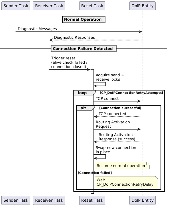
3.5.1.10. Connection Management
The CDA manages DoIP TCP connections with automatic recovery from connection failures. Per-Gateway Connection Architecture Each DoIP gateway has a single TCP connection that is shared by all ECUs behind that gateway. The connection is split into independent sender and receiver tasks that coordinate to avoid simultaneous read/write operations. All ECUs behind a gateway are multiplexed by their logical addresses over this shared connection. Connection Reset and Recovery A connection reset is triggered by:
The reset process:
Connection Reset and Recovery¶ |
3.5.1.11. DoIP Error Handling
The DoIP communication layer handles various error conditions that can occur during connection establishment, routing activation, and diagnostic message exchange. Error Categories
|
3.5.2. UDS Communication (DoIP)
The UDS (Unified Diagnostic Services) application layer sits above the DoIP transport layer and implements the request-response protocol defined in ISO 14229. It handles service payload construction, response matching, negative response code processing, tester present session keepalive, and functional group communication.
Communication parameters control timing, retry behavior, and tester present generation. These are sourced from the diagnostic database (MDD files) and may vary per logical link.
3.5.2.1. Communication Parameters
The UDS application layer is parameterized through a set of communication parameters (COM parameters) that control response timeouts, NRC handling policies, and tester present behavior. These parameters are sourced from the diagnostic database (MDD files) and can vary per logical link. Response Timing Parameters
NRC Handling Parameters
Tester Present Parameters
Note When these parameters are sourced from MDD files, multiple files could define different values for the same logical address due to duplicated logical addresses. |
3.5.2.2. Request-Response Flow
The UDS application layer implements the request-response flow using per-ECU semaphores for serialization, a SID-specific lookup table for response matching, and a layered retry strategy split between the UDS and DoIP layers. Per-ECU Semaphore A semaphore with a permit count of 1 is allocated per ECU logical address. Because the key is the logical address, ECUs that share a logical address (e.g., before variant detection) implicitly share the same semaphore. The semaphore is acquired before the request is sent and held for the entire send-and-receive cycle, including any NRC-driven waiting or retransmission. It is released only after the final response is received or an error occurs. Request Transmission The UDS layer constructs a payload containing the tester source address, target ECU
address, and UDS request data. This payload is passed to the DoIP transport layer
for transmission. On DoIP-level transmission failure, retries are handled by the
transport layer per Response Matching Algorithm Before sending, the UDS layer extracts a prefix of the request payload whose length is determined by a SID-to-length lookup table. This prefix is used to match the eventual response:
For a positive response, the first byte equals the sent SID plus NRC 0x78, 0x21, and 0x94 are parsed at the DoIP layer and delivered to the UDS layer as typed response variants. These are processed by the NRC handling logic (see UDS NRC Handling (arch~uds-nrc-handling)) before SID matching is applied to the final response. Timeout and Retry Strategy The caller may optionally override the default response timeout. When NRC 0x78 is
received, the active timeout switches from
UDS Request-Response Flow¶ |
![@startuml
skinparam backgroundColor #FFFFFF
skinparam sequenceArrowThickness 2
participant "Caller" as Caller
participant "CDA\n(UDS Layer)" as UDS
participant "DoIP\nTransport" as DoIP
participant "ECU" as ECU
== Request ==
Caller -> UDS: UDS request (service, payload)
activate UDS
UDS -> UDS: Acquire per-ECU\nsemaphore (by logical addr)
note right: 10s timeout\nfor acquisition
UDS -> UDS: Extract request prefix\nfor response matching\n(length varies by SID)
UDS -> DoIP: ServicePayload\n[tester_addr, ecu_addr, data]
DoIP -> ECU: Diagnostic Message (0x8001)
ECU --> DoIP: Diagnostic Message ACK
== Response Matching ==
ECU --> DoIP: UDS response
DoIP --> UDS: Response data
alt Positive response (SID + 0x40 + echoed prefix)
UDS -> UDS: Prefix match confirmed
UDS --> Caller: Response data
else Negative response (0x7F + SID)
UDS -> UDS: SID match confirmed
UDS --> Caller: Negative response
else Unmatched response
UDS -> UDS: Log warning, discard
UDS -> UDS: Continue waiting\nfor matching response
end
UDS -> UDS: Release per-ECU\nsemaphore
deactivate UDS
@enduml](../_images/plantuml-eb6d0e4e13b0c851f6cf33279c170401fd0995fe.png)
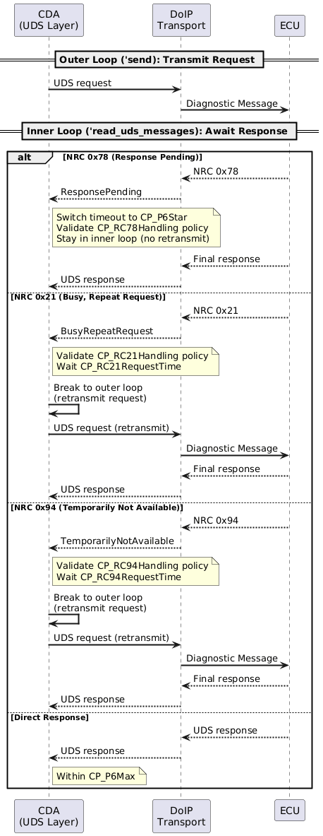
3.5.2.3. NRC Handling
The UDS application layer implements a dual-loop architecture for handling Negative Response Codes (NRCs). The outer loop handles retransmission (for NRC 0x21 and 0x94), while the inner loop handles continued waiting (for NRC 0x78). Each NRC type has an independent handling policy and timing configuration. Dual-Loop Architecture
NRC 0x78 – Response Pending When the ECU signals NRC 0x78, it has accepted the request but needs more time. The
CDA switches to the enhanced timeout
NRC 0x21 – Busy, Repeat Request When the ECU signals NRC 0x21, it is temporarily busy. The CDA waits for
NRC 0x94 – Temporarily Not Available When the ECU signals NRC 0x94, the requested resource is temporarily unavailable. The
CDA waits for
NRC Classification at Transport Layer NRC 0x78, 0x21, and 0x94 are parsed at the DoIP transport layer and delivered to the
UDS application layer as typed response variants ( Policy Validation Before acting on any NRC, the CDA validates the handling policy and checks the elapsed time against the configured completion timeout. If the policy is disabled or the timeout has been exceeded, the NRC is reported to the caller as a terminal negative response.
UDS NRC Handling – Dual-Loop Architecture¶ |
3.5.2.4. Tester Present
The CDA maintains active diagnostic sessions with ECUs by periodically sending UDS
Tester Present ( Lock-Driven Lifecycle Tester present tasks are tied to the SOVD lock mechanism:
If When a lock is released, the associated tester present tasks are stopped and the ECU’s session and security access state are reset. Duplicate Prevention Active tester present tasks are tracked in a HashMap keyed by ECU name. Before starting a new task, the system checks whether a task already exists for that ECU. Only one tester present task (physical or functional) can be active per ECU at any time. Task Implementation Each tester present task is a background async task that runs a periodic loop:
The interval uses a delay-on-miss strategy: if a tick is missed (e.g., due to slow sending), the next tick is delayed rather than bursting to catch up. Message Format The tester present message is constructed from The target address depends on the tester present type:
Functional Group Resolution When starting functional tester present, the system resolves the functional group to its member ECUs and starts individual tester present tasks for each gateway ECU in the group (ECUs whose logical address equals their gateway address). Each gateway receives its own dedicated background task sending to that gateway’s functional address. Error Handling
COM Parameter Usage All tester present COM parameters are loaded from the diagnostic database per ECU. The tester present task evaluates them as follows:
Note The current implementation uses only
Tester Present – Component Lock
Tester Present – Functional Group Lock¶ |
![@startuml
skinparam backgroundColor #FFFFFF
skinparam sequenceArrowThickness 2
participant "SOVD\nLock Manager" as LM
participant "CDA\n(UDS Layer)" as UDS
participant "DoIP\nTransport" as DoIP
participant "ECU" as ECU
LM -> UDS: acquire component lock (ECU)
UDS -> UDS: check_tester_present_active(ECU)
note right: No existing task found
UDS -> UDS: Start physical TP task\n(interval = CP_TesterPresentTime)
activate UDS #LightBlue
loop Every CP_TesterPresentTime
UDS -> DoIP: [0x3E, 0x00] to ECU\nphysical address
DoIP -> ECU: Tester Present
ECU --> DoIP: [0x7E, 0x00]
DoIP --> UDS: Tester Present Response
end
note over LM, ECU: This shows the typical flow.\nActual message content, timing, and response\nhandling depend on the CP_TesterPresent*\ncommunication parameters.
LM -> UDS: release component lock (ECU)
UDS -> UDS: Stop physical TP\ntask for ECU
deactivate UDS
@enduml](../_images/plantuml-973290a0bc8be6f7a5ad491051fa104641f7e5ce.png)
![@startuml
skinparam backgroundColor #FFFFFF
skinparam sequenceArrowThickness 2
participant "SOVD\nLock Manager" as LM
participant "CDA\n(UDS Layer)" as UDS
participant "DoIP\nTransport" as DoIP
participant "ECU A\n(Gateway)" as ECUA
LM -> UDS: acquire functional group lock
UDS -> UDS: Resolve group to\ngateway ECUs
UDS -> UDS: Start functional TP task\nfor ECU A (gateway)
activate UDS #LightGreen
loop Every CP_TesterPresentTime
UDS -> DoIP: [0x3E, 0x80] to ECU A\nfunctional address
DoIP -> ECUA: Tester Present
ECUA --> DoIP: ACK
end
LM -> UDS: release functional group lock
UDS -> UDS: Stop functional TP\ntask for ECU A
deactivate UDS
@enduml](../_images/plantuml-ac0f8be85d83a5dc44339a828509912caff36b64.png)
3.5.2.5. Functional Communication
The CDA supports functional group communication, where a single UDS request is sent to multiple ECUs simultaneously using functional addressing. ECUs are grouped by their gateway, and each gateway receives one functional request with responses collected from all ECUs behind it in parallel. Functional Group Resolution A functional group is resolved to its member ECUs from the diagnostic database. The following filters are applied:
Grouping by Gateway ECUs in the functional group are grouped by their gateway logical address:
Each gateway group produces one diagnostic request targeted at the gateway’s functional
address ( Parallel Gateway Communication When a functional group spans multiple gateways, the CDA sends to all gateways in parallel. For each gateway, the flow is:
Response Collection After the gateway accepts the functional request (DoIP ACK), the DoIP transport layer
demultiplexes incoming responses by source address. Each ECU behind the gateway has its
own receive channel, allowing responses to be collected concurrently. ECUs that do not
respond within No NRC Handling on Functional Path Unlike physical (unicast) communication, the functional communication path does not implement UDS-level NRC 0x21/0x78/0x94 handling. NRC responses on the functional path are returned as-is to the caller.
UDS Functional Communication Flow¶ |
![@startuml
skinparam backgroundColor #FFFFFF
skinparam sequenceArrowThickness 2
participant "Caller" as Caller
participant "CDA\n(UDS Layer)" as UDS
participant "DoIP Transport\n(Gateway 1)" as GW1
participant "ECU A\n(behind GW1)" as ECUA
participant "ECU B\n(behind GW1)" as ECUB
participant "DoIP Transport\n(Gateway 2)" as GW2
participant "ECU C\n(behind GW2)" as ECUC
== Resolve Functional Group ==
Caller -> UDS: Functional group request
activate UDS
UDS -> UDS: Resolve group to\nonline ECUs
UDS -> UDS: Group ECUs by\ngateway address
== Parallel Send to Gateways ==
par Gateway 1
UDS -> GW1: Diagnostic Message\n[functional_addr, UDS request]
GW1 --> UDS: ACK
par Collect Responses
GW1 -> ECUA: Forward UDS request
GW1 -> ECUB: Forward UDS request
ECUA --> GW1: UDS response
GW1 --> UDS: Response (ECU A)
ECUB --> GW1: UDS response
GW1 --> UDS: Response (ECU B)
end
else Gateway 2
UDS -> GW2: Diagnostic Message\n[functional_addr, UDS request]
GW2 --> UDS: ACK
GW2 -> ECUC: Forward UDS request
ECUC --> GW2: UDS response
GW2 --> UDS: Response (ECU C)
end
UDS --> Caller: Aggregated results\n{ECU A: response, ECU B: response,\nECU C: response}
deactivate UDS
note right of Caller: ECUs that do not respond\nwithin CP_P6Max are reported\nas individual timeouts
@enduml](../_images/plantuml-444b574380a4adacab43dd1190c43da092c8f054.png)
3.6. Diagnostic Tester
The Diagnostic Tester component provides the core functionality for communicating with vehicle ECUs using UDS (Unified Diagnostic Services) over DoIP (Diagnostics over IP). This document defines its architecture.
3.6.1. Startup Behavior
3.6.1.1. Startup Sequence
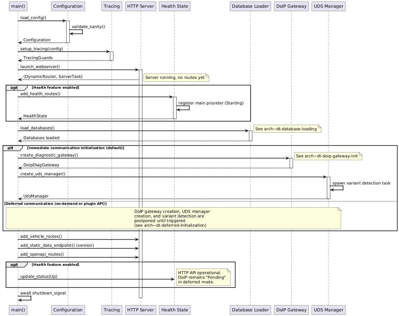
The CDA startup is orchestrated by the main application entry point, which coordinates initialization of all subsystems in a defined order to ensure proper dependency resolution and graceful degradation on partial failures. Component Initialization Order The startup sequence proceeds through the following phases:
Shutdown Signal Handling A shareable shutdown signal is created and propagated to all long-running tasks. This enables coordinated shutdown when receiving SIGTERM or Ctrl+C at any startup phase, including during database loading and DoIP initialization.
Startup Component Interaction¶ |
3.6.1.2. Database Loading
Diagnostic databases (MDD files) are loaded in parallel to minimize startup time, with careful handling of duplicates and failures to ensure robust operation. Note Database loading always occurs during startup, regardless of the initialization mode. Even when deferred initialization is configured, MDD files are loaded immediately so that the SOVD API can expose ECU metadata (names, capabilities) before communication is established. Only the DoIP gateway creation and variant detection are deferred. Parallel Loading Strategy The database loader discovers all chunk_size = file_count / (parallel_load_tasks + 1)
The number of parallel load tasks is configurable. Processing larger files first ensures optimal utilization of parallel workers, as smaller files naturally fill remaining capacity. Per-File Processing For each MDD file, the loader:
Duplicate ECU Handling When multiple MDD files define the same ECU name:
After loading, ECUs sharing the same logical address (from different database files with different ECU names) are identified and tracked for variant detection disambiguation. Health Status Integration When health monitoring is enabled (see Health Monitoring (arch~dt-health-monitoring)), a database health provider is registered with initial status “Starting”. After loading completes:
Failure Isolation Individual MDD file loading failures are logged but do not prevent other files from loading. The loader continues processing all discovered files regardless of individual failures. |
3.6.1.3. DoIP Gateway Initialization
The DoIP gateway establishes communication with vehicle DoIP entities through a discovery and connection establishment protocol defined in ISO 13400. Note When deferred initialization is configured (see Deferred Initialization (arch~dt-deferred-initialization)), the entire DoIP gateway initialization described below is postponed until a trigger event occurs. When health monitoring is enabled, the health provider for the DoIP component remains in “Pending” state until initialization is triggered. Socket Creation A UDP socket is created and bound to the configured tester address and gateway port. The socket is configured with:
Vehicle Identification The gateway broadcasts a Vehicle Identification Request (VIR) to Subnet Filtering VAM responses are filtered based on the configured subnet mask. Only responses from IP addresses
within the tester’s subnet (determined by Gateway-to-ECU Mapping For each discovered gateway (identified by its logical address in the VAM), the system:
Spontaneous VAM Listener After initial discovery, a background task continuously listens for spontaneous VAM broadcasts. This handles scenarios where:
When a new VAM is received, the system establishes a connection (if not already connected) and triggers variant detection for the associated ECUs.
DoIP Gateway Discovery and Connection¶ |
3.6.1.4. Deferred Initialization
The CDA supports deferred initialization of ECU communication to enable scenarios where the HTTP API must be available before vehicle communication begins. Dynamic Router Architecture The HTTP server is launched with a dynamic router that supports adding routes after the server has started. This enables:
Initialization Triggers When deferred initialization is configured, DoIP gateway creation and ECU discovery are postponed until one of the following triggers:
Pre-initialization State While initialization is deferred:
Initialization Sequence Once triggered, initialization proceeds identically to the immediate initialization path: DoIP gateway creation, TCP connection establishment, UDS manager creation, and variant detection. Upon completion, SOVD routes are registered and, when health monitoring is enabled, health status transitions to “Up”. |
3.6.1.5. Health Monitoring
Health monitoring is an optional build-time feature that provides an HTTP endpoint for querying the aggregate and per-component health status of the CDA. Health status is only retrievable through the health endpoint when this feature is enabled at build time. Feature Enabled Behavior When the health feature is enabled:
Feature Disabled Behavior When the health feature is disabled at build time:
Component Health Providers When enabled, the following component health providers are registered:
Health Status Transitions
Component Health State Transitions¶ |
![@startuml
skinparam backgroundColor #FFFFFF
skinparam stateArrowThickness 2
[*] --> Pending : Component registered\n(initialization not yet started)
Pending --> Starting : Initialization begins
Starting --> Up : Initialization successful
Starting --> Failed : Initialization failed
state Pending {
}
state Starting {
}
state Up {
}
state Failed {
}
note right of Pending
Used for components whose initialization
is deferred (e.g., DoIP gateway when
deferred initialization is configured).
Pending and Starting both contribute to
an overall "Starting" aggregate status.
end note
@enduml](../_images/plantuml-7a2532ed7f4e18ca7fcc5fd545d9eba27eb01a3b.png)
3.6.2. ECU Detection and Variant Detection
3.6.2.1. ECU Discovery
ECU discovery establishes the mapping between diagnostic database definitions (MDD files) and physical DoIP communication endpoints. Database-to-Gateway Mapping During database loading, each ECU’s logical gateway address is extracted from the MDD. A mapping structure is built that associates each gateway logical address with the list of ECU logical addresses accessible through it. VAM Matching When a VAM is received, its logical address is matched against the ECU addresses from loaded databases. A match indicates that the ECU defined in the MDD is physically present and reachable through the responding gateway. Connection Association For discovered ECUs, the system maintains:
This structure enables routing diagnostic messages to the correct gateway and ECU. ECU Name Mapping A secondary mapping tracks ECU names to logical addresses for supporting SOVD API requests that reference ECUs by name rather than address. This associates each gateway logical address with the list of ECU names accessible through it. Duplicate Address Detection ECUs sharing the same logical address (from different MDD files with different ECU names) are tracked as potential duplicates. Each ECU manager stores references to other ECU names that share the same address. Variant detection determines which ECU definition is correct for the physical ECU. |
3.6.2.2. Variant Detection
Variant detection identifies the correct ECU software variant from multiple possible definitions by querying the ECU and matching responses against defined patterns. Detection Request Channel A message channel connects the DoIP gateway to the UDS manager for variant detection coordination. When a VAM is received (either during startup or from spontaneous announcements), the gateway sends a list of ECU names requiring variant detection through this channel. Asynchronous Detection Variant detection runs asynchronously to avoid blocking startup. A dedicated task receives ECU names from the channel and spawns individual detection tasks per ECU. This enables parallel variant detection across multiple ECUs. Detection Process For each ECU requiring variant detection:
Duplicate Resolution When multiple ECU definitions share the same logical address, variant detection determines which definition matches the physical ECU. The matching ECU transitions to Online state; non-matching ECUs with the same address transition to Duplicate state and their databases are effectively disabled. Fallback Behavior When variant detection fails to find a matching pattern:
|
3.6.2.3. ECU States
ECU state management tracks the lifecycle of each ECU from registration through variant detection and ongoing communication. States The following states are maintained:
The distinction between Offline and Disconnected reflects whether the ECU has ever been successfully communicated with. An ECU that fails its first contact attempt transitions to Offline; an ECU that was previously Online, NoVariantDetected, or Disconnected and loses communication transitions to Disconnected. State Storage ECU state is maintained within the ECU manager structure, which wraps the diagnostic database and adds runtime state information. The state is queryable through the SOVD API component endpoints. State Transitions State transitions are triggered by:
Concurrent Access ECU state is protected by a read-write lock to enable concurrent read access from multiple API handlers while ensuring exclusive write access during state transitions. The database map associates each ECU name with its concurrency-protected state manager. State Query The SOVD API exposes ECU state through the component collection endpoint. Clients can query individual ECU status or list all ECUs with their current states. The state is included in the component response to inform clients of ECU availability. |
3.6.3. Error Handling
The CDA implements graceful degradation during startup to maximize availability even when individual components fail. Error Type Hierarchy Application errors are categorized through a structured error type hierarchy. The following error types are relevant during startup:
Additionally, the following error types may occur during runtime after startup has completed:
Component Health Integration When health monitoring is enabled (see Health Monitoring (arch~dt-health-monitoring)), component failures are reflected through health provider status transitions. Health providers and their status transitions are defined in the health monitoring architecture. Graceful Degradation Behaviors
Shutdown Handling Shutdown signals (SIGTERM, Ctrl+C) are handled gracefully at any startup phase:
All shutdown paths ensure resources are properly released through structured cleanup and tracing guards that flush logs on drop. |
3.7. Plugins
3.7.1. Overview
The plugin system in the Classic Diagnostic Adapter (CDA) provides extensibility for vendor-specific functionality that cannot be standardized across all implementations. Plugins enable customization of security mechanisms, authentication flows, and other domain-specific requirements while maintaining the core diagnostic functionality.
The plugin architecture is designed around trait-based interfaces that allow runtime polymorphism and flexible configuration. This approach ensures that the CDA can adapt to different deployment environments and vendor requirements without requiring modifications to the core codebase.
3.7.2. Security Plugin Architecture
The security plugin system is the primary plugin implementation within the CDA, responsible for authentication, authorization, and access control for REST calls.
Core Traits
The security plugin system is built around several key traits that define the plugin interface:
SecurityPlugin
The main trait that combines authentication and authorization capabilities:
pub trait SecurityPlugin: Any + SecurityApi + AuthApi {
    fn as_auth_plugin(&self) -> &dyn AuthApi;
    fn as_security_plugin(&self) -> &dyn SecurityApi;
}
AuthApi
Provides access to user claims:
pub trait AuthApi: Send + Sync + 'static {
    fn claims(&self) -> Box<&dyn Claims>;
}
SecurityApi
Validates diagnostic service requests based on security policies:
pub trait SecurityApi: Send + Sync + 'static {
    fn validate_service(&self, service: &DiagnosticService) -> Result<(), DiagServiceError>;
}
SecurityPluginLoader
Combines initialization and authorization request handling capabilities:
pub trait SecurityPluginLoader:
    SecurityPluginInitializer + AuthorizationRequestHandler + Default + 'static
{
}
3.7.3. Plugin Lifecycle
The security plugin follows a specific lifecycle during request processing:
Middleware Registration: The security plugin middleware is registered during router setup
Request Interception: Each incoming request passes through the security middleware
Plugin Initialization: The plugin extracts authentication information from request headers and creates the plugin instance
Request Processing: The initialized plugin instance is made available to route handlers
Service Validation: Diagnostic services are validated against security policies before execution
3.7.4. Future Extensions
The plugin architecture is designed to support additional plugin types:
3.7.4.1. Logging Plugins
Custom log formatting and destinations
Integration with external logging systems
Performance metrics collection
3.7.4.2. Safety Plugins
Functional safety compliance validation
Diagnostic session safety checks
Emergency shutdown procedures
3.7.4.3. Custom Endpoint Plugins
Vendor-specific API extensions
Additional data formats and protocols
Integration with external systems
3.7.5. Diagnostic Database Update Plugin
Endpoints and Security By default, all modifying actions to any endpoint require an exclusive vehicle lock. It must be ensured, that no diagnostic operations are in progress, when the “Apply” action is triggered - this includes functional and component locks. Only the subject of the lock is allowed to use the endpoints. This ensures that the database isn’t used while it is being updated, and that no 3rd party could add additional files to the update while it is being prepared, which could lead to security issues. This behavior and additional security requirements must be modifiable through a trait provided to the plugin, to support more specific OEM requirements for security and individual environments during the update process. The diagnostic database update plugin must provide the following bulk-data categories/endpoints:
Note The following query parameters must be supported for the GET endpoints:
Configuration File Support In addition to MDD database files (
Only one All GET endpoints ( The HTTP handler implementation for these endpoints resides in
Coupled MDD and Configuration Updates When an MDD file update requires a simultaneous configuration change (e.g., a new MDD file
introduces changes that require updated communication parameters in the CDA configuration), both
files must be uploaded to Warning There is no guaranteed atomic coupling when MDD and configuration updates are applied in separate executions. Applying them independently means they take effect at different points in time, which may leave the system in a partially updated state during the interval between the two applies. Users must account for this by uploading all related files (MDD and configuration) in the
same Limitations to bulk-data operations For Security reasons, none of the endpoints should allow retrieval of the files by default - there may be an option
to enable it. Adding or deleting files must only be allowed in the File Handling The id for the files within the diagnostic database update plugin must be the file name, to ensure consistency when files are overwritten, deleted, or added. File names must be handled case-insensitively on all operating systems to make usage regardless of OS consistent, to avoid duplicated entries, and to allow case-insensitive paths for deletion. There must be an option to normalize file names to the name of the ECU they belong to, to ensure consistency and to avoid duplicated entries for the same ECU with different file names. Files must be verifiable through a The verification includes, but is not limited to, signature verification, hash verification, and version checks of the currently active database, as well as the new one. Application of the update To delete all pending updates from To apply all the pending updates to the current diagnostic database, an additional endpoint is required:
The same endpoint must also be made available as Execution Lifecycle Only one execution can be in-flight at a time. Starting a new execution while one is already running must be rejected with a conflict error. Execution entries are retained in memory and remain queryable via
The list endpoint After applying, or rolling back the diagnostic database, the new database must be active immediately, without requiring a restart of the CDA, and the old state must be available as a backup until the next update is applied, the backup is deleted, or a cleanup is initiated. The state of nextupdate must also be reset after applying or rolling back, to ensure that pending updates aren’t reapplied unintentionally after a rollback, and to ensure that the state of the next update is consistent with the currently active database. Atomicity Every action must be atomically applied, meaning that if any part of the action fails, the entire action must be rolled back, and the state of the diagnostic database while the adapter is running must be consistent with either the state before the action, or the state after the action, but not a partially applied state. This also applies to power cycles and crashes during the application of the update, to ensure this, journaling and transactional file handling can be used, but the exact mechanism is up to the implementation of the plugin. This may require flushing filesystem caches frequently to guarantee consistency. |
3.7.6. DLT Logging Plugin
The DLT logging integration adds an optional tracing output that forwards application log and trace events to the AUTOSAR Diagnostic Log and Trace (DLT) daemon via the DLT system library. Integration into the Tracing Stack The DLT output is realized as an additional subscriber layer within the existing layered tracing architecture. The tracing system composes multiple output layers (terminal, file, OpenTelemetry, DLT) into a single subscriber. When DLT is enabled, its layer receives the same tracing events as all other layers and translates them into DLT log messages.
Compile-Time Feature Gating The entire DLT integration is guarded by a compile-time feature flag. When the feature is not active:
When the feature is active, the DLT layer is only added to the tracing subscriber if the runtime configuration also enables it. Runtime Enablement At startup, the tracing initialization checks the DLT configuration. If DLT support is compiled in but disabled in the configuration, the DLT layer is not registered, and no connection to the DLT daemon is established. Log Level Mapping Application trace levels are mapped to their DLT equivalents by the DLT subscriber layer, ensuring that severity-based filtering in DLT tooling works as expected. |
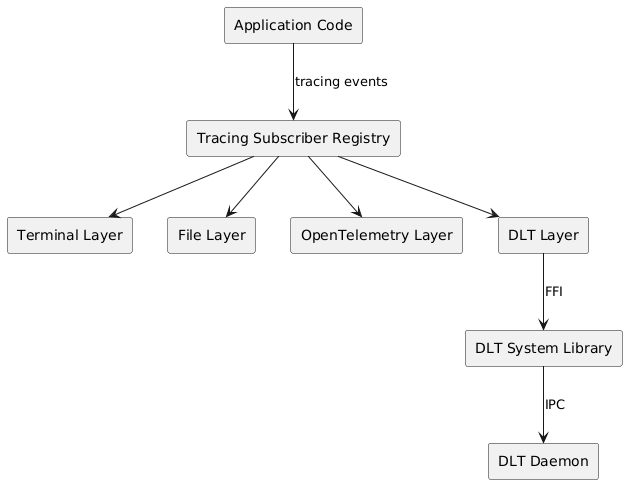
The DLT logging configuration is part of the application-wide logging configuration and is deserialized from the configuration file. The configuration contains the following parameters:
The application ID is validated against DLT protocol constraints during initialization. An invalid application ID (e.g. exceeding 4 characters) prevents the DLT layer from being created and results in a startup error. |
Each subsystem of the CDA annotates its tracing spans with a DLT context identifier. The DLT subscriber layer reads the context identifier from the span metadata and uses it to route the log message to the appropriate DLT context. A helper macro is provided to annotate tracing spans with context identifiers. The macro is feature-gated:
The following context identifiers are used by the CDA subsystems:
|