1.1. Introduction
The Classic Diagnostics Adapters purpose is to provide an SOVD API for legacy ECUs. Communication with legacy ECUs is facilitated by utilizing UDS. It must support DoIP, and may support additional transports in the future.
This documentation also utilizes sphinx-needs for traceability between requirements, architecture, design, implementation and tests.
1.1.1. DoIP Discovery and Connection Establishment
DoIP (Diagnostics over IP, ISO 13400) is the transport protocol used by the CDA to communicate with vehicle ECUs. Before diagnostic messages can be exchanged, two phases must complete: discovery and connection establishment.
1.1.1.1. Discovery
Discovery uses UDP broadcast to locate DoIP entities (gateways) on the network. The CDA sends a Vehicle Identification Request (VIR) to the broadcast address on the DoIP port (13400). Each DoIP entity that receives the request responds with a Vehicle Announcement Message (VAM) containing its IP address, logical address, and vehicle identification data (VIN, EID, GID). Responses are filtered to only accept entities within the same subnet as the CDA. After initial discovery, a background listener continues to receive spontaneous VAMs so that gateways coming online later are detected automatically.
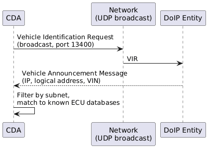
DoIP Discovery (simplified)
1.1.1.2. Connection Establishment
Once a DoIP entity is discovered, the CDA establishes a TCP connection to it and performs routing activation to register itself as a diagnostic tester. Only after successful routing activation can UDS diagnostic messages be exchanged. If the entity requires an encrypted connection, the CDA transparently falls back to TLS on port 3496 and repeats the routing activation over the secured channel.
![@startuml
skinparam backgroundColor #FFFFFF
participant "CDA" as CDA
participant "DoIP Entity" as GW
CDA -> GW: TCP connect (port 13400)
GW --> CDA: TCP connected
CDA -> GW: Routing Activation Request\n(tester logical address)
alt Activation successful
GW --> CDA: Routing Activation Response\n[SuccessfullyActivated]
note right of CDA: Ready for\ndiagnostic messages
else TLS required
GW --> CDA: Routing Activation Response\n[TLS required]
CDA -> GW: TCP connect (TLS port 3496)
CDA <-> GW: TLS handshake
CDA -> GW: Routing Activation Request
GW --> CDA: Routing Activation Response\n[SuccessfullyActivated]
note right of CDA: Ready for\ndiagnostic messages (TLS)
end
@enduml](../_images/plantuml-f5c546cbaf89998256472d4a745ff0bdf8079f5c.png)
DoIP Connection Establishment (simplified)
For a detailed description of the DoIP communication layer including message framing, communication parameters, error handling, and alive-check behaviour, see the DoIP Communication section in the Architecture.
1.1.2. UDS Diagnostic Communication
UDS (Unified Diagnostic Services, ISO 14229) is the application-layer protocol used to interact with ECUs. It defines a set of services, each identified by a Service Identifier (SID), that allow a tester to read data, write configuration, control ECU functions, and manage diagnostic sessions. The CDA acts as the tester, translating SOVD API calls into UDS requests and forwarding them over the DoIP transport.
1.1.2.1. Data-Driven Approach via MDD
The CDA uses a data-driven approach: all knowledge about ECUs – their logical addresses, supported services, data identifiers, routines, communication timing parameters, and session configuration – is loaded at runtime from MDD (Marvelous Diagnostic Description) files. These files are the diagnostic description database for the vehicle and contain the full definition of what each ECU supports.
This means the CDA itself contains no hard-coded ECU knowledge. Instead it reads the MDD files on startup and configures all communication parameters (timeouts, retry counts, tester present behavior, addressing) per ECU from those files. Adding support for a new ECU or updating its diagnostic description requires only a new or updated MDD file – no code changes.
A client (e.g. a diagnostic tool or test script) communicates with the CDA exclusively through the SOVD REST API using JSON over HTTP. The CDA uses the MDD data to translate each incoming JSON request into the appropriate UDS service call and returns the ECU’s response as a JSON reply – the client never deals with raw UDS bytes directly.
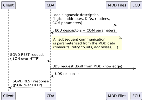
MDD-driven ECU configuration (simplified)
1.1.2.2. Essential UDS Service Identifiers
The table below lists the UDS services most relevant to the CDA’s operation. Each service is
invoked by sending a request frame whose first byte is the SID; a positive response carries
SID + 0x40 as its first byte.
SID |
Service |
Purpose |
|---|---|---|
|
DiagnosticSessionControl |
Switch the ECU into a specific diagnostic session (e.g., default, extended, programming). Many services are only available in non-default sessions. |
|
ECUReset |
Trigger a hard or soft reset of the ECU. |
|
ClearDiagnosticInformation |
Erase stored Diagnostic Trouble Codes (DTCs) from ECU memory. |
|
ReadDTCInformation |
Read Diagnostic Trouble Codes and their associated status from the ECU. |
|
ReadDataByIdentifier |
Read one or more data values referenced by a 2-byte Data Identifier (DID), such as sensor readings, calibration values, or version strings. |
|
SecurityAccess |
Authenticate the tester to unlock ECU functions that require elevated access (seed/key challenge-response). |
|
WriteDataByIdentifier |
Write a value to a DID, such as updating configuration data or calibration parameters. |
|
RoutineControl |
Start, stop, or request the result of a named routine on the ECU (identified by a 2-byte Routine Identifier, RID). |
|
RequestDownload |
Initiate a data download (flash programming) transfer from the tester to the ECU. |
|
RequestUpload |
Initiate a data upload transfer from the ECU to the tester. |
|
TransferData |
Transfer a data block as part of an ongoing download or upload sequence. |
|
RequestTransferExit |
Conclude a data transfer sequence. |
|
TesterPresent |
Keep the current non-default diagnostic session alive. The CDA sends this periodically while a diagnostic lock is held so the ECU does not time out the session. |
1.1.2.3. UDS Request-Response Flow
Every UDS exchange follows the same basic pattern: the CDA sends a request frame (SID + payload),
the DoIP gateway acknowledges receipt at the transport layer, and the ECU eventually replies with
either a positive response (SID + 0x40) or a negative response (0x7F + SID + NRC).
Certain Negative Response Codes (NRCs) signal transient conditions – for example, NRC 0x78
(Response Pending) means the ECU needs more time – and the CDA handles these automatically
according to configurable policies sourced from the MDD files.
![@startuml
skinparam backgroundColor #FFFFFF
participant "CDA" as CDA
participant "DoIP Gateway" as GW
participant "ECU" as ECU
CDA -> GW: UDS Request\n[SID + payload]
GW --> CDA: DoIP ACK
GW -> ECU: Forward request
alt Positive response
ECU --> GW: [SID+0x40 + data]
GW --> CDA: UDS Response
note right of CDA: Success
else Negative response
ECU --> GW: [0x7F, SID, NRC]
GW --> CDA: UDS Negative Response
note right of CDA: Error or retry\ndepending on NRC
else Response pending (NRC 0x78)
ECU --> GW: [0x7F, SID, 0x78]
GW --> CDA: ResponsePending
note right of CDA: Wait with extended\ntimeout, keep listening
ECU --> GW: Final response
GW --> CDA: UDS Response
end
@enduml](../_images/plantuml-c8372fd433a6bc0c34d0fc44dc1a5d4bcb18aa57.png)
UDS request-response (simplified)
For a detailed description of the UDS communication layer including NRC handling policies, tester present behavior, functional group communication, and all communication parameters, see the UDS Communication section in the Architecture.