3.4.1. DoIP Communication

DoIP Communication is described in the ISO 13400 standard. The CDA implements DoIP as transport layer for UDS diagnostic communication with vehicle ECUs.

The communication parameters depend on the logical link used for the communication, filtered by configuration and actual ECU detection/availability.

3.4.1.1. Protocol Versions

Software Architecture: DoIP Protocol Version Support arch~doip-protocol-versions
status: draft

The CDA supports multiple DoIP protocol versions as defined in ISO 13400-2. The protocol version is included in the DoIP header of every message to indicate which version of the standard the message conforms to.

Supported Versions

Value

Version

Standard

0x01

ISO 13400-2:2010

Initial release

0x02

ISO 13400-2:2012

Default version used by the CDA

0x03

ISO 13400-2:2019

Updated release

0x04

ISO 13400-2:2019/Amd1

Amendment 1

0xFF

Default / any

Wildcard version identifier

Version Selection

The protocol version is configurable. The default version is ISO 13400-2:2012 (0x02). UDP broadcast messages for vehicle identification shall use the default/any version (0xFF), as the tester does not know which protocol version the DoIP entity supports at discovery time.

3.4.1.2. Message Framing

Software Architecture: DoIP Message Framing arch~doip-message-framing
status: draft
links incoming: req~doip-message-framing

All DoIP messages share a common 8-byte header followed by a variable-length payload. The codec layer is responsible for encoding outgoing messages and decoding incoming messages from the byte stream.

Header Structure

Byte(s)

Field

Description

0

Protocol Version

DoIP protocol version identifier

1

Inverse Version

Bitwise inverse of the protocol version (0xFF XOR version), used for integrity check

2-3

Payload Type

16-bit identifier of the payload type (big-endian)

4-7

Payload Length

32-bit length of the payload in bytes (big-endian), excluding the header

Supported Payload Types

Value

Payload Type

Direction

Transport

0x0000

Generic NACK

Response

TCP/UDP

0x0001

Vehicle Identification Request

Request

UDP

0x0002

Vehicle Identification Request (by EID)

Request

UDP

0x0003

Vehicle Identification Request (by VIN)

Request

UDP

0x0004

Vehicle Announcement Message (VAM)

Response

UDP

0x0005

Routing Activation Request

Request

TCP

0x0006

Routing Activation Response

Response

TCP

0x0007

Alive Check Request

Request

TCP

0x0008

Alive Check Response

Response

TCP

0x8001

Diagnostic Message

Request/Response

TCP

0x8002

Diagnostic Message ACK

Response

TCP

0x8003

Diagnostic Message NACK

Response

TCP

Decoding Behavior

The decoder reads the 8-byte header first. If insufficient data is available, it waits for more data to arrive on the stream. Once the header is complete, it reads the number of bytes indicated by the payload length field and dispatches to the appropriate payload parser based on the payload type.

3.4.1.3. Communication Parameters

Software Architecture: DoIP Communication Parameters arch~doip-communication-parameters
status: draft

The DoIP communication layer is parameterized through a set of communication parameters (COM parameters) that control addressing, timeouts, and retry behavior. These parameters are sourced from the diagnostic database (MDD files) and can vary per logical link.

DoIP communication parameters

Name

Function

Default value

Comment

CP_DoIPLogicalGatewayAddress

Logical address of a DoIP entity. In case of a directly reachable DoIP entity it is equal to CP_DoIPLogicalEcuAddress, otherwise data is sent via this address to the CP_DoIPLogicalEcuAddress

0

CP_DoIPLogicalEcuAddress

Logical/Physical address of the ECU

0

CP_DoIPLogicalFunctionalAddress

Functional address of the ECU

0

CP_DoIPLogicalTesterAddress

Logical address of the tester

0

CP_DoIPNumberOfRetries

Number of retries for specific diagnostic message NACKs

3 (for OUT_OF_MEMORY)

Retry count is configured per NACK code

CP_DoIPDiagnosticAckTimeout

Maximum time the tester waits for an ACK or NACK from the DoIP entity

1s

CP_DoIPRetryPeriod

Period between retries after specific NACK conditions are encountered

200ms

CP_DoIPRoutingActivationTimeout

Maximum time allowed for the ECU’s routing activation response

30s

CP_RepeatReqCountTrans

Number of retries in case of a transmission error, receive error, or transport layer timeout

3

CP_DoIPConnectionTimeout

Timeout after which a connection attempt should have been successful

30s

CP_DoIPConnectionRetryDelay

Delay before attempting to reconnect

5s

CP_DoIPConnectionRetryAttempts

Number of attempts to retry connection before giving up

100

Note

When these parameters are sourced from MDD files, multiple files could define different values for the same logical address due to duplicated logical addresses.

3.4.1.4. Vehicle Identification

Software Architecture: Vehicle Identification arch~doip-vehicle-identification
status: draft

Vehicle identification is the process by which the CDA discovers DoIP entities on the network. It uses UDP broadcast to solicit Vehicle Announcement Messages from all reachable DoIP entities.

Discovery Process

  1. A UDP socket is created and bound to the configured tester address and gateway port (default: 13400). The socket is configured with broadcast capability and address reuse.

  2. A Vehicle Identification Request (VIR, payload type 0x0001) is broadcast to 255.255.255.255 on the gateway port.

  3. Vehicle Announcement Messages (VAM, payload type 0x0004) are collected within a timeout window.

  4. VAM responses are filtered by subnet mask: only responses from IP addresses within the tester’s subnet (tester_address AND tester_subnet) are accepted.

  5. Each accepted VAM is matched against known ECU logical addresses from the diagnostic databases.

Vehicle Announcement Message Content

Each VAM contains:

  • Vehicle Identification Number (VIN, 17 bytes)

  • Logical address of the DoIP entity (2 bytes)

  • Entity Identification (EID, 6 bytes)

  • Group Identification (GID, 6 bytes)

  • Further action code (routing activation required or no further action)

  • Optional VIN/GID synchronization status

Spontaneous VAM Listener

After initial discovery, a background task continuously listens on the gateway port for spontaneous VAM broadcasts, subject to the configured spontaneous VAM handling mode (see Spontaneous VAM Handling Mode (arch~doip-vam-handling-mode)). When active, this handles:

  • Gateways coming online after the initial VIR broadcast

  • Gateways reconnecting after a temporary disconnection

When a new or known VAM is received, the system establishes or re-uses the connection and triggers variant detection for the associated ECUs.

@startuml
skinparam backgroundColor #FFFFFF
skinparam sequenceArrowThickness 2

participant "CDA" as CDA
participant "UDP Socket\n(port 13400)" as UDP
participant "DoIP Entity A" as GWA
participant "DoIP Entity B" as GWB

== Initial Discovery ==
CDA -> UDP: Create socket\n(broadcast, address reuse)
CDA -> UDP: VIR broadcast to\n255.255.255.255:13400

UDP -> GWA: Vehicle Identification\nRequest (0x0001)
UDP -> GWB: Vehicle Identification\nRequest (0x0001)

GWA --> UDP: VAM (0x0004)\n[logical_addr, VIN, EID, GID]
GWB --> UDP: VAM (0x0004)\n[logical_addr, VIN, EID, GID]

CDA -> CDA: Filter VAMs by\nsubnet mask
CDA -> CDA: Match logical addresses\nto MDD databases

== Spontaneous Listener (background) ==
CDA -> UDP: Listen for spontaneous VAMs
...
GWA --> UDP: Spontaneous VAM\n(entity came online)
UDP --> CDA: New VAM received
CDA -> CDA: Establish connection\nand trigger variant detection
@enduml

Vehicle Identification Sequence

3.4.1.5. Spontaneous VAM Handling Mode

Software Architecture: Spontaneous VAM Handling Mode arch~doip-vam-handling-mode
status: draft

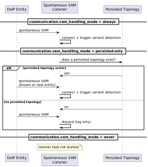
The spontaneous VAM listener’s behavior is governed by the configured communication.vam_handling_mode:

  • always (default): the listener is active and any spontaneous VAM whose logical address matches a known ECU from the diagnostic databases triggers connection establishment and variant detection, as described in the Spontaneous VAM Listener section above.

  • persisted-only: the listener is active only while a persisted ECU topology exists (see ECU List Persistence (arch~dt-ecu-list-persistence)); this is a one-time check of whether the persistence bucket is present, not a per-VAM lookup of the responding entity’s logical address. When a topology exists, spontaneous VAMs are handled identically to always mode, including VAMs from entities not yet present in the persisted topology – such entities are discovered and added like any other. When no persisted topology exists, the listener discards all spontaneous VAMs (logged only) until a topology has been persisted (via startup detection or networkreset, see Vehicle Topology Plugin - R... (arch~plugin-vehicle-topology-reset-persistence)), at which point it starts handling spontaneous VAMs normally without requiring a restart. When communication.ecu_list_persistence.enabled is false (see ECU List Persistence (arch~dt-ecu-list-persistence)), a persisted topology can never exist, so this mode is functionally identical to never in that configuration.

  • never: the spontaneous VAM listener task is not started. Gateways can only be (re-)discovered via an explicit networkreset execution (see Vehicle Topology Plugin - R... (arch~plugin-vehicle-topology-reset-persistence)) or via the DoIP connection retry mechanism operating on already-established connections (see CP_DoIPConnectionRetryDelay / CP_DoIPConnectionRetryAttempts).

Independent of vam_handling_mode, the spontaneous VAM listener task itself is only started once ECU/DoIP communication has actually been initialized (see Communication Initializatio... (arch~dt-deferred-initialization)). While init_mode is OnDemand or Disabled and its trigger has not yet fired, no listener task exists, regardless of the configured mode.

@startuml
skinparam backgroundColor #FFFFFF
skinparam sequenceArrowThickness 2

participant "DoIP Entity" as GW
participant "Spontaneous VAM\nListener" as Listener
participant "Persisted Topology" as Persist

== communication.vam_handling_mode = always ==
GW --> Listener: spontaneous VAM
Listener -> Listener: connect + trigger variant detection

== communication.vam_handling_mode = persisted-only ==
Listener -> Persist: does a persisted topology exist?
alt persisted topology exists
    Persist --> Listener: yes
    GW --> Listener: spontaneous VAM\n(known or new entity)
    Listener -> Listener: connect + trigger variant detection
else no persisted topology
    Persist --> Listener: no
    GW --> Listener: spontaneous VAM
    Listener -> Listener: discard (log only)
end

== communication.vam_handling_mode = never ==
note over Listener: listener task not started
@enduml

Spontaneous VAM Handling Mode

3.4.1.6. Connection Establishment

Software Architecture: DoIP Connection Establishment arch~doip-connection-establishment
status: draft

After a DoIP entity is discovered via vehicle identification, a TCP connection is established to enable diagnostic communication.

TCP Connection

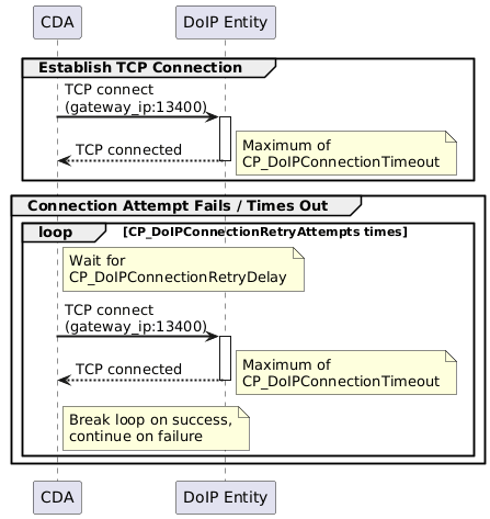
A TCP connection is initiated to the discovered gateway IP address on the configured gateway port (default: 13400). The connection attempt is bounded by the CP_DoIPConnectionTimeout parameter.

Retry Behavior

If the initial connection attempt fails or times out, the system retries according to:

  • Wait CP_DoIPConnectionRetryDelay between attempts

  • Retry up to CP_DoIPConnectionRetryAttempts times

  • On success: break the retry loop and proceed

  • On exhaustion of all retries: report connection failure

If the connection was initiated as part of a diagnostic request, a timeout error is reported to the caller.

@startuml
skinparam backgroundColor #FFFFFF
skinparam sequenceArrowThickness 2

participant "CDA" as CDA
participant "DoIP Entity" as ECU

group Establish TCP Connection
    CDA -> ECU: TCP connect\n(gateway_ip:13400)
    activate ECU
    ECU --> CDA: TCP connected
    note right: Maximum of\nCP_DoIPConnectionTimeout
    deactivate ECU
end

group Connection Attempt Fails / Times Out
    loop CP_DoIPConnectionRetryAttempts times
        note right of CDA: Wait for\nCP_DoIPConnectionRetryDelay
        CDA -> ECU: TCP connect\n(gateway_ip:13400)
        activate ECU
        ECU --> CDA: TCP connected
        deactivate ECU
        note right: Maximum of\nCP_DoIPConnectionTimeout
        note right of CDA: Break loop on success,\ncontinue on failure
    end
end
@enduml

DoIP Connection Establishment

3.4.1.7. Routing Activation

Software Architecture: Routing Activation arch~doip-routing-activation
status: draft

After establishing a TCP connection, routing activation must be performed before diagnostic messages can be exchanged. This registers the tester’s logical address with the DoIP entity.

Request

The CDA sends a Routing Activation Request (payload type 0x0005) containing:

  • Source address: the tester’s logical address (2 bytes)

  • Activation type: Default (0x00)

  • Reserved buffer (4 bytes, set to zero)

Response Handling

The response contains an activation code that determines the outcome:

Routing Activation Response Codes

Code

Meaning

CDA Behavior

0x10

Successfully activated

Proceed with diagnostic communication

0x11

Activated, confirmation required

Treat as success

0x07

Denied, encrypted TLS connection required

Fall back to TLS connection (see TLS Connection Support (arch~doip-tls))

0x00

Denied, unknown source address

Report routing error

0x01

Denied, all TCP sockets full

Report routing error

0x02

Denied, TCP socket already connected

Report routing error

0x03

Denied, source already active

Report routing error

0x04

Denied, missing authentication

Report routing error

0x05

Denied, rejected confirmation

Report routing error

0x06

Denied, unsupported activation type

Report routing error

The routing activation response must be received within CP_DoIPRoutingActivationTimeout.

@startuml
skinparam backgroundColor #FFFFFF
skinparam sequenceArrowThickness 2

participant "CDA" as CDA
participant "DoIP Entity" as ECU

== Routing Activation ==
CDA -> ECU: Routing Activation Request (0x0005)\n[tester_addr, type=Default]
activate ECU
note right: Maximum of\nCP_DoIPRoutingActivationTimeout

alt Activation Successful (0x10)
    ECU --> CDA: Routing Activation Response\n[code=SuccessfullyActivated]
    deactivate ECU
    note right of CDA: Connection ready\nfor diagnostics

else TLS Required (0x07)
    ECU --> CDA: Routing Activation Response\n[code=DeniedEncryptedTLSRequired]
    deactivate ECU
    CDA -> CDA: Close plain TCP connection

    CDA -> ECU: TCP connect to TLS port (3496)
    activate ECU
    CDA <-> ECU: TLS Handshake
    CDA -> ECU: Routing Activation Request (0x0005)\n[tester_addr, type=Default]
    ECU --> CDA: Routing Activation Response\n[code=SuccessfullyActivated]
    deactivate ECU
    note right of CDA: TLS connection ready\nfor diagnostics

else Denied (any other code)
    ECU --> CDA: Routing Activation Response\n[code=Denied*]
    deactivate ECU
    note right of CDA: Report routing error
end
@enduml

Routing Activation Sequence

3.4.1.8. TLS Connection Support

Software Architecture: TLS Connection Support arch~doip-tls
status: draft
links incoming: req~doip-tls

The CDA supports TLS-secured DoIP connections as defined in ISO 13400. TLS is activated as a fallback when a DoIP entity requires encrypted communication.

TLS Activation Trigger

TLS is not used by default. It is activated when a Routing Activation Response returns the code DeniedRequestEncryptedTLSConnection (0x07). The CDA then:

  1. Closes the plain TCP connection

  2. Establishes a new TCP connection to the TLS port (default: 3496)

  3. Performs the TLS handshake

  4. Re-sends the Routing Activation Request over the secured connection

TLS Configuration

  • Minimum TLS version: TLS 1.2

  • Maximum TLS version: TLS 1.3

  • Certificate verification can be enforced, with configurable trusted CA certificates

3.4.1.9. Diagnostic Message Exchange

Software Architecture: Diagnostic Message Exchange arch~doip-diagnostic-message
status: draft

Diagnostic messages carry UDS (Unified Diagnostic Services) data between the CDA and ECUs through the DoIP transport layer.

Sending a Diagnostic Message

  1. The connection for the target ECU’s gateway is looked up by gateway logical address.

  2. The ECU lock is acquired to serialize requests per ECU.

  3. Any pending messages in the receive buffer are cleared.

  4. The Diagnostic Message (0x8001) is sent containing the tester’s source address, the target ECU address, and the UDS payload.

  5. On transmission failure, the message is retried up to CP_RepeatReqCountTrans times.

ACK/NACK Handling

After sending, the CDA waits for an acknowledgement within CP_DoIPDiagnosticAckTimeout:

  • Diagnostic Message ACK (0x8002): The message was accepted by the DoIP entity. The ACK may contain the original message for verification. If the contained message does not match the sent message, the CDA continues waiting for the correct ACK.

  • Diagnostic Message NACK (0x8003): The message was rejected. The NACK code indicates the reason. Depending on the code and CP_DoIPNumberOfRetries, the message may be retried after CP_DoIPRetryPeriod.

  • Generic NACK (0x0000): A protocol-level error occurred. Reported as error.

  • Timeout: No ACK or NACK received within the timeout. Reported as timeout error.

Receiving the Diagnostic Response

After a successful ACK, the CDA waits for the diagnostic response. All responses (including pending NRCs) arrive as raw DiagnosticResponse::Msg events on the per-ECU broadcast channel. doip_event_to_transport() classifies the three pending-lifecycle NRCs with pending_nrc_from_raw() and forwards them as TransportResponse::Pending. It wraps every other response in TransportResponse::UdsResponse with uds_response_from_raw().

The only exception is TesterPresent NRCs (7F 3E xx), which are intercepted at the DoIP decoding layer and routed to a dedicated TesterPresentNRC event so the receiver can log-and-drop them without polluting per-ECU channels.

Multiple intermediate responses may be received before the final response:

  • NRC 0x78 (Response Pending): The ECU needs more time. Classified at the transport boundary and handled by the UDS layer per CP_RC78Handling and CP_RC78CompletionTimeout, using the enhanced timeout CP_P6Star.

  • NRC 0x21 (Busy, Repeat Request): The ECU is busy. Classified at the transport boundary and handled per CP_RC21Handling, CP_RC21CompletionTimeout, and CP_RC21RequestTime.

  • NRC 0x94 (Temporarily Not Available): Classified at the transport boundary and handled per CP_RC94Handling, CP_RC94CompletionTimeout, and CP_RC94RequestTime.

  • Final Response: The complete UDS response is returned to the caller.

NRC Classification in the DoIP Receive Path

The following diagram traces the complete path of a UDS negative response through the DoIP receive pipeline, from raw TCP bytes to the typed TransportResponse variant that the UDS application layer consumes:

@startuml
skinparam backgroundColor #FFFFFF
skinparam componentStyle rectangle

title "DoIP NRC Classification Flow"

package "TCP Stream" as TCP {
  (Raw DoIP frame\n0x8001 DiagnosticMessage) as Raw
}

package "connections.rs: try_read()" as DecodePkg {
  (Decode DoIP header\nand payload) as Decode
  (is_tester_present_nrc?) as TpCheck
}

package "connection_receiver.rs\nhandle_ok_response()" as RoutePkg {
  (Broadcast to per-ECU\nchannel by source_address) as Route
  (Log and drop) as Drop
}

package "lib.rs\ndoip_event_to_transport()" as ClassifyPkg {
  (pending_nrc_from_raw?) as NrcCheck
}

package "TransportResponse" as RespPkg {
  (TransportResponse::Pending\n{PendingNrc}) as Pending
  (TransportResponse::UdsResponse\n{ServicePayload}) as Final
}

Raw --> Decode
Decode --> TpCheck

TpCheck --> Route : [NO]\nDiagnosticResponse::Msg
TpCheck --> Drop : [YES]\nTesterPresentNRC(code)

Route --> NrcCheck : Per-ECU broadcast\nchannel

NrcCheck --> Pending : [YES]\n0x78 / 0x21 / 0x94
NrcCheck --> Final : [NO]\nAll other responses

note bottom of Drop
    TesterPresent NRCs (7F 3E xx)
    from functional keep-alive are
    intercepted here and never
    reach the per-ECU channel.
    The receiver logs them at
    debug level and discards them.
end note

note bottom of NrcCheck
    Shared classification using
    pending_nrc_from_raw() from
    cda-interfaces/src/uds.rs.
    Identical logic for both
    DoIP and CAN transports.
end note

note bottom of Final
    This path carries both
    positive responses and
    non-pending negative responses
    (all NRCs except 0x78/0x21/0x94).
end note
@enduml

DoIP NRC Classification Flow

The classification functions are defined in cda-interfaces/src/uds.rs:

  • is_tester_present_nrc(data) – checks for 0x7F 0x3E xx

  • pending_nrc_from_raw(data, source_address) – classifies 0x78/0x21/0x94 into PendingNrc variants and returns None for all other responses

  • uds_response_from_raw(data, source_address, target_address) – wraps any remaining response (positive or non-pending negative) into a ServicePayload

Functional Addressing

For functional group communication, a single diagnostic message is sent to the gateway using the functional address (CP_DoIPLogicalFunctionalAddress). Responses are collected from multiple ECUs simultaneously. ECUs that do not respond within the timeout are reported individually.

Auto-ACK on Receive

When the CDA receives a diagnostic message from a DoIP entity, it automatically sends a Diagnostic Message ACK back. This behavior is configurable.

@startuml
skinparam backgroundColor #FFFFFF
skinparam sequenceArrowThickness 2

participant "CDA" as CDA
participant "DoIP Entity\n(Gateway)" as GW
participant "ECU" as ECU

== Send Diagnostic Request ==
CDA -> GW: Diagnostic Message (0x8001)\n[tester_addr -> ecu_addr, UDS request]
activate GW

alt ACK received
    GW --> CDA: Diagnostic Message ACK (0x8002)
    note right: Within\nCP_DoIPDiagnosticAckTimeout

else NACK received
    GW --> CDA: Diagnostic Message NACK (0x8003)\n[nack_code]
    note right of CDA: Retry based on\nCP_DoIPNumberOfRetries\nand CP_DoIPRetryPeriod
    deactivate GW
end

== Await Diagnostic Response ==
GW -> ECU: Forward UDS request
activate ECU

alt Response Pending (NRC 0x78)
    ECU --> GW: NRC 0x78 (Response Pending)
    GW --> CDA: Diagnostic Message (0x8001)\n[NRC 0x78]
    note right of CDA: Continue waiting per\nCP_RC78Handling\nwith CP_P6Star timeout

    ECU --> GW: UDS positive response
    GW --> CDA: Diagnostic Message (0x8001)\n[UDS response]
    deactivate ECU
    deactivate GW
    CDA -> GW: Diagnostic Message ACK (0x8002)

else Direct Response
    ECU --> GW: UDS response
    GW --> CDA: Diagnostic Message (0x8001)\n[UDS response]
    deactivate ECU
    deactivate GW
    CDA -> GW: Diagnostic Message ACK (0x8002)
end
@enduml

Diagnostic Message Exchange (Physical Addressing)

@startuml
skinparam backgroundColor #FFFFFF
skinparam sequenceArrowThickness 2

participant "CDA" as CDA
participant "DoIP Entity\n(Gateway)" as GW
participant "ECU A" as ECUA
participant "ECU B" as ECUB

== Functional Request (one-to-many) ==
CDA -> GW: Diagnostic Message (0x8001)\n[tester_addr -> functional_addr,\nUDS request]
activate GW
GW --> CDA: Diagnostic Message ACK (0x8002)

GW -> ECUA: Forward UDS request
activate ECUA
GW -> ECUB: Forward UDS request
activate ECUB

== Collect Responses from Multiple ECUs ==
ECUA --> GW: UDS response
GW --> CDA: Diagnostic Message (0x8001)\n[ECU A response]
deactivate ECUA
CDA -> GW: Diagnostic Message ACK (0x8002)

ECUB --> GW: UDS response
GW --> CDA: Diagnostic Message (0x8001)\n[ECU B response]
deactivate ECUB
deactivate GW
CDA -> GW: Diagnostic Message ACK (0x8002)

note right of CDA: ECUs that do not respond\nwithin timeout are reported\nas individual timeouts
@enduml

Diagnostic Message Exchange (Functional Addressing)

3.4.1.10. Alive Check

Software Architecture: Alive Check arch~doip-alive-check
status: draft
links incoming: req~doip-alive-check

The alive check mechanism verifies that the TCP connection to a DoIP entity is still active during periods of inactivity.

Periodic Check

When no diagnostic messages have been sent on a connection for a defined idle interval, the CDA sends an Alive Check Request (0x0007) to the DoIP entity.

Response Handling

ECU Support Detection

Not all DoIP entities implement the alive check mechanism. The CDA tracks whether a DoIP entity has ever responded to an Alive Check Request. A missing response is only treated as a connection loss when the entity has previously demonstrated support by sending at least one Alive Check Response. If the entity has never responded to an alive check, the absence of a response is not considered a failure.

3.4.1.11. Connection Management

Software Architecture: DoIP Connection Management arch~doip-connection-management
status: draft

The CDA manages DoIP TCP connections with automatic recovery from connection failures.

Per-Gateway Connection Architecture

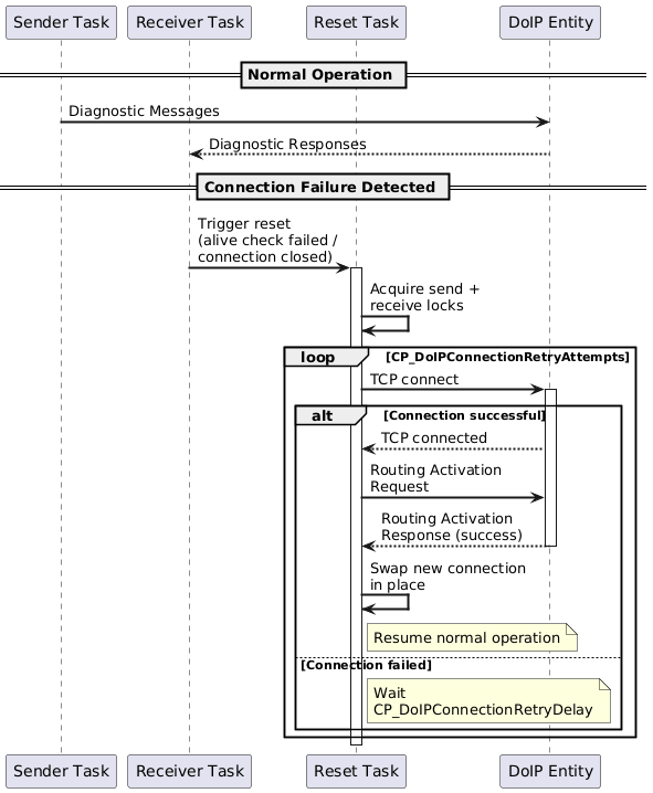
Each DoIP gateway has a single TCP connection that is shared by all ECUs behind that gateway. The connection is split into independent sender and receiver tasks that coordinate to avoid simultaneous read/write operations. All ECUs behind a gateway are multiplexed by their logical addresses over this shared connection.

Connection Reset and Recovery

A connection reset is triggered by:

  • Failed alive check (no response within timeout)

  • Connection closed by the remote side

  • Send failure on the connection

The reset process:

  1. Acquire exclusive access to both the send and receive sides of the connection

  2. Attempt to re-establish the TCP connection and perform routing activation

  3. On failure: retry with CP_DoIPConnectionRetryDelay up to CP_DoIPConnectionRetryAttempts

  4. On success: swap the new connection in place and resume normal operation

  5. On exhaustion of all retries: the connection is considered permanently lost

@startuml
skinparam backgroundColor #FFFFFF
skinparam sequenceArrowThickness 2

participant "Sender Task" as ST
participant "Receiver Task" as RT
participant "Reset Task" as RESET
participant "DoIP Entity" as GW

== Normal Operation ==
ST -> GW: Diagnostic Messages
GW --> RT: Diagnostic Responses

== Connection Failure Detected ==
RT -> RESET: Trigger reset\n(alive check failed /\nconnection closed)
activate RESET

RESET -> RESET: Acquire send +\nreceive locks

loop CP_DoIPConnectionRetryAttempts
    RESET -> GW: TCP connect
    activate GW

    alt Connection successful
        GW --> RESET: TCP connected
        RESET -> GW: Routing Activation\nRequest
        GW --> RESET: Routing Activation\nResponse (success)
        deactivate GW
        RESET -> RESET: Swap new connection\nin place
        note right of RESET: Resume normal operation
    else Connection failed
        note right of RESET: Wait\nCP_DoIPConnectionRetryDelay
        deactivate GW
    end
end
deactivate RESET
@enduml

Connection Reset and Recovery

3.4.1.12. DoIP Error Handling

Software Architecture: DoIP Error Handling arch~doip-error-handling
status: draft
links incoming: req~doip-error-handling

The DoIP communication layer handles various error conditions that can occur during connection establishment, routing activation, and diagnostic message exchange.

Error Categories

Category

Condition

Behavior

Connection Closed

TCP connection unexpectedly closed by remote side

Trigger connection reset

Decode Error

Received message could not be decoded

Log error and continue

Invalid Message

Unexpected message type received in current state

Report error to caller

Connection Timeout

TCP connect did not complete within CP_DoIPConnectionTimeout

Retry per connection retry parameters

Routing Error

Routing activation denied (non-TLS denial codes)

Report routing error

Send Failure

Message could not be written to the TCP stream

Retry per CP_RepeatReqCountTrans, trigger reset on persistent failure

ACK Timeout

No ACK/NACK within CP_DoIPDiagnosticAckTimeout

Report timeout to caller

Diagnostic NACK

DoIP entity rejected diagnostic message

Retry per CP_DoIPNumberOfRetries with CP_DoIPRetryPeriod delay, based on NACK code