3.4.3. UDS Communication
The UDS (Unified Diagnostic Services) application layer sits above the transport layer and implements the request-response protocol defined in ISO 14229. It handles service payload construction, response matching, negative response code processing, tester present session keepalive, and functional group communication.
Communication parameters control timing, retry behavior, and tester present generation. These are sourced from the diagnostic database (MDD files) and may vary per logical link.
3.4.3.1. Communication Parameters
The UDS application layer is parameterized through a set of communication parameters (COM parameters) that control response timeouts, NRC handling policies, and tester present behavior. These parameters are sourced from the diagnostic database (MDD files) and can vary per logical link. Response Timing Parameters
NRC Handling Parameters
Tester Present Parameters
Note When these parameters are sourced from MDD files, multiple files could define different values for the same logical address due to duplicated logical addresses. |
3.4.3.2. Request-Response Flow
The UDS application layer implements the request-response flow using per-ECU semaphores for serialization, a SID-specific lookup table for response matching, and a layered retry strategy split between the UDS and transport layers. Per-ECU Semaphore A semaphore with a permit count of 1 is allocated per ECU logical address. Because the key is the logical address, ECUs that share a logical address (e.g., before variant detection) implicitly share the same semaphore. The semaphore is acquired before the request is sent and held for the entire send-and-receive cycle, including any NRC-driven waiting or retransmission. It is released only after the final response is received or an error occurs. Request Transmission The UDS layer constructs a payload containing the tester source address, target ECU address, and UDS request data. This payload is passed to the selected transport for transmission. Transport-specific transmission failures are returned to the UDS layer. Response Matching Algorithm Before sending, the UDS layer extracts a prefix of the request payload whose length is determined by a SID-to-length lookup table. This prefix is used to match the eventual response:
For a positive response, the first byte equals the sent SID plus NRC 0x78, 0x21, and 0x94 are classified at the transport boundary by the shared
Timeout and Retry Strategy The caller may optionally override the default response timeout. When NRC 0x78 is
received, the active timeout switches from Each application-layer attempt uses a fresh response channel. When an attempt is retried (transmission error, receive error, or plain timeout with no response), the previous attempt’s channel is dropped, which signals the gateway’s per-request task to stop. This ensures a retry is gated solely by that attempt’s own timeout: a late response or error from a prior, superseded attempt can no longer leak into the current attempt and trigger an immediate (sub-timeout) retry. Dropping the previous attempt’s channel only signals its gateway task to stop; it
does not by itself guarantee that task has finished releasing whatever per-ECU
resource it holds (e.g. a DoIP connection mutex, or - for CAN, which has no
equivalent per-connection lock - an ISO-TP socket bound to the same CAN ID pair).
To close that gap,
UDS Request-Response Flow¶ |
![@startuml
skinparam backgroundColor #FFFFFF
skinparam sequenceArrowThickness 2
participant "Caller" as Caller
participant "CDA\n(UDS Layer)" as UDS
participant "Transport\n(DoIP or CAN)" as Transport
participant "ECU" as ECU
== Request ==
Caller -> UDS: UDS request (service, payload)
activate UDS
UDS -> UDS: Acquire per-ECU\nsemaphore (by logical addr)
note right: 10s timeout\nfor acquisition
UDS -> UDS: Extract request prefix\nfor response matching\n(length varies by SID)
UDS -> Transport: ServicePayload\n[tester_addr, ecu_addr, data]
Transport -> ECU: Transport request
== Response Matching ==
ECU --> Transport: UDS response
Transport --> UDS: TransportResponse
alt Positive response (SID + 0x40 + echoed prefix)
UDS -> UDS: Prefix match confirmed
UDS --> Caller: Response data
else Negative response (0x7F + SID)
UDS -> UDS: SID match confirmed
UDS --> Caller: Negative response
else Unmatched response
UDS -> UDS: Log warning, discard
UDS -> UDS: Continue waiting\nfor matching response
end
UDS -> UDS: Release per-ECU\nsemaphore
deactivate UDS
@enduml](../../_images/plantuml-bf9816dade8be0bd59758f20ac8cf1d10cc25019.png)
3.4.3.3. NRC Handling
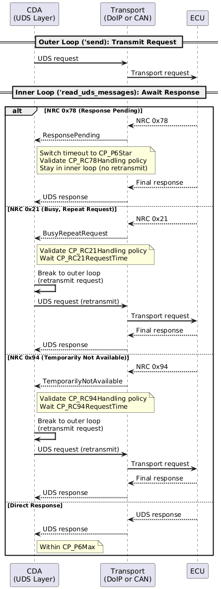
The UDS application layer implements a dual-loop architecture for handling Negative Response Codes (NRCs). The outer loop handles retransmission (for NRC 0x21 and 0x94), while the inner loop handles continued waiting (for NRC 0x78). Each NRC type has an independent handling policy and timing configuration. Dual-Loop Architecture
NRC 0x78 – Response Pending When the ECU signals NRC 0x78, it has accepted the request but needs more time. The
CDA switches to the enhanced timeout
NRC 0x21 – Busy, Repeat Request When the ECU signals NRC 0x21, it is temporarily busy. The CDA waits for
NRC 0x94 – Temporarily Not Available When the ECU signals NRC 0x94, the requested resource is temporarily unavailable. The
CDA waits for
NRC Classification NRC 0x78, 0x21, and 0x94 are classified at the transport boundary by the shared
NRC Data Flow – End-to-End Classification Pipeline¶ Policy Validation Before acting on any NRC, the CDA validates the handling policy and checks the elapsed time against the configured completion timeout. If the policy is disabled or the timeout has been exceeded, the NRC is reported to the caller as a terminal negative response.
UDS NRC Handling – Dual-Loop Architecture¶ The following diagram shows the complete lifecycle of a UDS response byte from the ECU, through the transport classification, through the UDS retry logic, and finally to the service-layer NRC interpretation:
Complete NRC Response Lifecycle¶ |
![@startuml
skinparam backgroundColor #FFFFFF
skinparam componentStyle rectangle
title "UDS NRC Classification Pipeline"
package "Transport Layer" {
[DoIP TCP Reader\n(try_read)] as DoipRead
[CAN ISO-TP Reader\n(exchange.read_response)] as CanRead
}
package "Receiver / Per-ECU Routing" {
[DoIP connection_receiver\nBypass TesterPresent NRCs\nRoute by source_address] as DoipRecv
[CAN Gateway\nExtend ISO-TP deadline\non pending NRC] as CanGw
}
package "Shared UDS Boundary\ncda-interfaces/src/uds.rs" {
(pending_nrc_from_raw) as PendingCheck
(uds_response_from_raw) as FinalWrap
}
package "TransportResponse\necugateway.rs" {
[TransportResponse::Pending\n{PendingNrc}] as PendingResp
[TransportResponse::UdsResponse\n{ServicePayload}] as FinalResp
}
package "UDS Transport Layer\ncda-comm-uds/src/transport.rs" {
[send_with_raw_payload\n'read_uds_messages loop] as UdsTransport
}
package "UDS Service Layer\ncda-core" {
[convert_from_uds()\nMap raw bytes to\nDiagServiceResponse] as Convert
[as_nrc()\nExtract NRC code +\ndescription + SID] as AsNrc
[extract_nrc_from_raw_data()\nFallback for unmapped\nnegative responses] as ExtractNrc
}
DoipRead --> DoipRecv : DiagnosticResponse::Msg
CanRead --> CanGw : Raw UDS bytes
DoipRecv --> PendingCheck : data, source_address
CanGw --> PendingCheck : data, source_address
PendingCheck --> PendingResp : [YES] 0x78 / 0x21 / 0x94
PendingCheck --> FinalWrap : [NO]
FinalWrap --> FinalResp : ServicePayload
PendingResp --> UdsTransport : Retry or extend wait
FinalResp --> UdsTransport : Final response
UdsTransport --> Convert : Ok(ServicePayload)
Convert --> AsNrc : DiagServiceResponse.as_nrc()
Convert --> ExtractNrc : Fallback when\nno mapped response data
note bottom of DoipRecv
TesterPresent NRCs (7F 3E xx)
are intercepted in connections.rs
before any per-ECU routing.
end note
note bottom of CanGw
CAN extends the ISO-TP
socket deadline when a
pending NRC arrives, then
forwards to the same
classification function.
end note
note bottom of PendingResp
0x78 ResponsePending:
extend timeout (CP_P6Star)
keep waiting in inner loop
0x21 BusyRepeatRequest:
sleep CP_RC21RequestTime
retransmit via outer loop
0x94 TemporarilyNotAvailable:
sleep CP_RC94RequestTime
retransmit via outer loop
end note
note bottom of FinalResp
Carries all non-pending responses:
- Positive responses (SID | 0x40)
- Non-pending NRCs (0x22, 0x31, 0x33, ...)
end note
@enduml](../../_images/plantuml-18133b1a544e3afdd9ebbea8b47a6a5d862f25b9.png)
![@startuml
skinparam backgroundColor #FFFFFF
skinparam sequenceArrowThickness 2
participant "ECU" as ECU
participant "Transport\n(DoIP / CAN)" as Transport
participant "Classification\npending_nrc_from_raw()" as Classify
participant "UDS Transport\nsend_with_raw_payload()" as UdsTx
participant "UDS Service\nconvert_from_uds()" as UdsSvc
== ECU sends raw UDS response ==
ECU -> Transport: Raw bytes\n[0x7F, SID, NRC]
== Transport classification ==
Transport -> Classify: data, source_address
alt Pending NRC (0x78 / 0x21 / 0x94)
Classify -> Transport: TransportResponse::Pending(PendingNrc)
Transport -> UdsTx: PendingNrc
group Dual-Loop NRC Handling
alt 0x78 (ResponsePending)
UdsTx -> UdsTx: Switch timeout to CP_P6Star
note right: Stay in inner loop,\nwait for final response
UdsTx -> Transport: Continue reading
Transport -> ECU: (no retransmit)
ECU -> Transport: Final response
Transport -> UdsTx: TransportResponse::UdsResponse
else 0x21 (BusyRepeatRequest)
UdsTx -> UdsTx: Validate CP_RC21Handling
note right: Sleep CP_RC21RequestTime,\nthen retransmit
UdsTx -> Transport: Retransmit request
Transport -> ECU: Diagnostic Message
ECU -> Transport: Final response
Transport -> UdsTx: TransportResponse::UdsResponse
else 0x94 (TemporarilyNotAvailable)
UdsTx -> UdsTx: Validate CP_RC94Handling
note right: Sleep CP_RC94RequestTime,\nthen retransmit
UdsTx -> Transport: Retransmit request
Transport -> ECU: Diagnostic Message
ECU -> Transport: Final response
Transport -> UdsTx: TransportResponse::UdsResponse
end
end
else Non-pending NRC or positive response
Classify -> Transport: TransportResponse::UdsResponse(ServicePayload)
Transport -> UdsTx: ServicePayload {data, addresses}
note right: Direct final response,\nno retry needed
end
== UDS Service Layer Interpretation ==
UdsTx -> UdsSvc: Ok(ServicePayload)
alt Positive response
UdsSvc -> UdsSvc: Match by SID + 0x40
UdsSvc --> Caller: Decoded response
else Negative response (NRC)
UdsSvc -> UdsSvc: as_nrc() or\nextract_nrc_from_raw_data()
note right: Returns MappedNRC\n{code, description, SID}
UdsSvc --> Caller: MappedNRC result
end
@enduml](../../_images/plantuml-bea64814f3ae6bfd0f2ebef00fa0a89399a9ce6b.png)
3.4.3.4. Tester Present
The CDA maintains active diagnostic sessions with ECUs by periodically sending UDS
Tester Present ( Lock-Driven Lifecycle Tester present tasks are tied to the SOVD lock mechanism:
If When a lock is released, the associated tester present tasks are stopped and the ECU’s session and security access state are reset. Releasing, expiring, or preempting a functional group lock also releases every component lock of the same client whose physical tester present it replaced, running their tester present stop and session/security reset as well. Releasing or expiring one of those component locks on its own, while the functional group lock still covers that ECU, stops no tester present task and resets no session/security state; the functional group lock still owns both until it is itself released. Duplicate Prevention Tester present state is tracked in a single map, keyed by (type, ECU), where each entry is either actively running or suspended (see Communication Disable and Re-enable below). Before starting a new task, the system checks whether an entry already exists for that key. Only one tester present task (physical or functional) can be active per ECU at any time; acquiring a functional group lock enforces this by stopping the component lock’s entry for a covered ECU once the functional group’s own entry is running. Task Implementation Each tester present task is a background async task that runs a periodic loop:
The interval uses a delay-on-miss strategy: if a tick is missed (e.g., due to slow sending), the next tick is delayed rather than bursting to catch up. Message Format The tester present message is constructed from The target address depends on the tester present type:
Functional Group Resolution When starting functional tester present, the system resolves the functional group to its member ECUs and starts individual tester present tasks for each gateway ECU in the group (ECUs whose logical address equals their gateway address). Each gateway receives its own dedicated background task sending to that gateway’s functional address. Error Handling
COM Parameter Usage All tester present COM parameters are loaded from the diagnostic database per ECU. The tester present task evaluates them as follows:
Communication Disable and Re-enable The tester present map (see Duplicate Prevention above) is the single record of tester present state: there is no separate snapshot. Each entry is either Running (the task is actively sending) or Suspended (communication is disabled, so nothing is sent, but the entry is kept so the task can be resumed). When communication is disabled, the Suspended entries are not resumed by the Session and security access resets follow the same pattern. Pending resets are kept
per ECU, each either Scheduled (a task resets the ECU once its delay has passed) or
Deferred. A reset that is due while communication is not enabled, for example
because a lock expired, sends nothing and requests no activation; it is recorded as
Deferred and reported to the caller as deferred. Note The runtime resolves
Tester Present – Component Lock
Tester Present – Functional Group Lock¶ |
![@startuml
skinparam backgroundColor #FFFFFF
skinparam sequenceArrowThickness 2
participant "SOVD\nLock Manager" as LM
participant "CDA\n(UDS Layer)" as UDS
participant "Transport\n(DoIP / CAN)" as Transport
participant "ECU" as ECU
LM -> UDS: acquire component lock (ECU)
UDS -> UDS: check_tester_present_active(ECU)
note right: No existing task found
UDS -> UDS: Start physical TP task\n(interval = CP_TesterPresentTime)
activate UDS #LightBlue
loop Every CP_TesterPresentTime
UDS -> Transport: [0x3E, 0x00] to ECU\nphysical address
Transport -> ECU: Tester Present
ECU --> Transport: [0x7E, 0x00]
Transport --> UDS: Tester Present Response
end
note over LM, ECU: This shows the typical flow.\nActual message content, timing, and response\nhandling depend on the CP_TesterPresent*\ncommunication parameters.
LM -> UDS: release component lock (ECU)
UDS -> UDS: Stop physical TP\ntask for ECU
deactivate UDS
@enduml](../../_images/plantuml-595db17d6f71fc47db626d790afdf11135d7551d.png)
![@startuml
skinparam backgroundColor #FFFFFF
skinparam sequenceArrowThickness 2
participant "SOVD\nLock Manager" as LM
participant "CDA\n(UDS Layer)" as UDS
participant "Transport\n(DoIP / CAN)" as Transport
participant "ECU A\n(Gateway)" as ECUA
LM -> UDS: acquire functional group lock
UDS -> UDS: Resolve group to\ngateway ECUs
UDS -> UDS: Start functional TP task\nfor ECU A (gateway)
activate UDS #LightGreen
loop Every CP_TesterPresentTime
UDS -> Transport: [0x3E, 0x80] to ECU A\nfunctional address
Transport -> ECUA: Tester Present
ECUA --> Transport: ACK
end
LM -> UDS: release functional group lock
UDS -> UDS: Stop functional TP\ntask for ECU A
deactivate UDS
@enduml](../../_images/plantuml-d95dcf272ab018753386eac767b779172ee4e7b9.png)
3.4.3.5. Functional Communication
The CDA supports functional group communication, where a single UDS request is sent to multiple ECUs simultaneously using functional addressing. ECUs are grouped by their gateway, and each gateway receives one functional request with responses collected from all ECUs behind it in parallel. Functional Group Resolution A functional group is resolved to its member ECUs from the diagnostic database. The following filters are applied:
Grouping by Gateway ECUs in the functional group are grouped by their gateway logical address:
Each gateway group produces one diagnostic request targeted at the gateway’s functional
address (e.g., Parallel Gateway Communication When a functional group spans multiple gateways, the CDA sends to all gateways in parallel. For each gateway, the flow is:
Response Collection After the gateway forwards the functional request, the transport layer
demultiplexes incoming responses by source address. Each ECU behind the gateway has its
own receive channel, allowing responses to be collected concurrently. ECUs that do not
respond within No NRC Handling on Functional Path Unlike physical (unicast) communication, the functional communication path does not implement UDS-level NRC 0x21/0x78/0x94 handling. NRC responses on the functional path are returned as-is to the caller.
UDS Functional Communication Flow¶ |
![@startuml
skinparam backgroundColor #FFFFFF
skinparam sequenceArrowThickness 2
participant "Caller" as Caller
participant "CDA\n(UDS Layer)" as UDS
participant "Transport\n(DoIP Gateway 1)" as GW1
participant "ECU A\n(behind GW1)" as ECUA
participant "ECU B\n(behind GW1)" as ECUB
participant "Transport\n(DoIP Gateway 2)" as GW2
participant "ECU C\n(behind GW2)" as ECUC
== Resolve Functional Group ==
Caller -> UDS: Functional group request
activate UDS
UDS -> UDS: Resolve group to\nonline ECUs
UDS -> UDS: Group ECUs by\ngateway address
== Parallel Send to Gateways ==
par Gateway 1
UDS -> GW1: Diagnostic Message\n[functional_addr, UDS request]
GW1 --> UDS: ACK
par Collect Responses
GW1 -> ECUA: Forward UDS request
GW1 -> ECUB: Forward UDS request
ECUA --> GW1: UDS response
GW1 --> UDS: Response (ECU A)
ECUB --> GW1: UDS response
GW1 --> UDS: Response (ECU B)
end
else Gateway 2
UDS -> GW2: Diagnostic Message\n[functional_addr, UDS request]
GW2 --> UDS: ACK
GW2 -> ECUC: Forward UDS request
ECUC --> GW2: UDS response
GW2 --> UDS: Response (ECU C)
end
UDS --> Caller: Aggregated results\n{ECU A: response, ECU B: response,\nECU C: response}
deactivate UDS
note right of Caller: ECUs that do not respond\nwithin CP_P6Max are reported\nas individual timeouts
@enduml](../../_images/plantuml-c4b855430d6b49a3e03bc5255fa4ef9b58d90166.png)